Miniature UV sensor utilizing a disposable flow cell

a flow cell and sensor technology, applied in the field of sensor utilizing a disposable flow cell, can solve the problems of inability to adapt to the above-mentioned disposable process equipment or to laboratory or small-scale process, and achieve the effect of accurate optical alignmen

Inactive Publication Date: 2012-05-17
ENDRESS HAUSER CONDUCTA GESELLSCHAFT FUER MESS UND REGELTECHNIK MBH CO KG
View PDF7 Cites 23 Cited by
  • Summary
  • Abstract
  • Description
  • Claims
  • Application Information

AI Technical Summary

Benefits of technology

[0018]In addition, both the first and second housing components can comprise a dowel pin extending from their second end walls which fit into corresponding mating holes in the second end walls, when the first and second housing components are engaged. This ensures accurate optical alignment of the optical detector and the light source, e.g. the solid state emitter.

Problems solved by technology

Heretofore, inline optical sensors for monitoring process media comprise a relatively complex structure that cannot easily be adapted to the aforementioned disposable process equipment or to laboratory or small-scale process conditions, respectively.

Method used


Image

  • Miniature UV sensor utilizing a disposable flow cell
  • Miniature UV sensor utilizing a disposable flow cell
  • Miniature UV sensor utilizing a disposable flow cell

Examples


Embodiment Construction

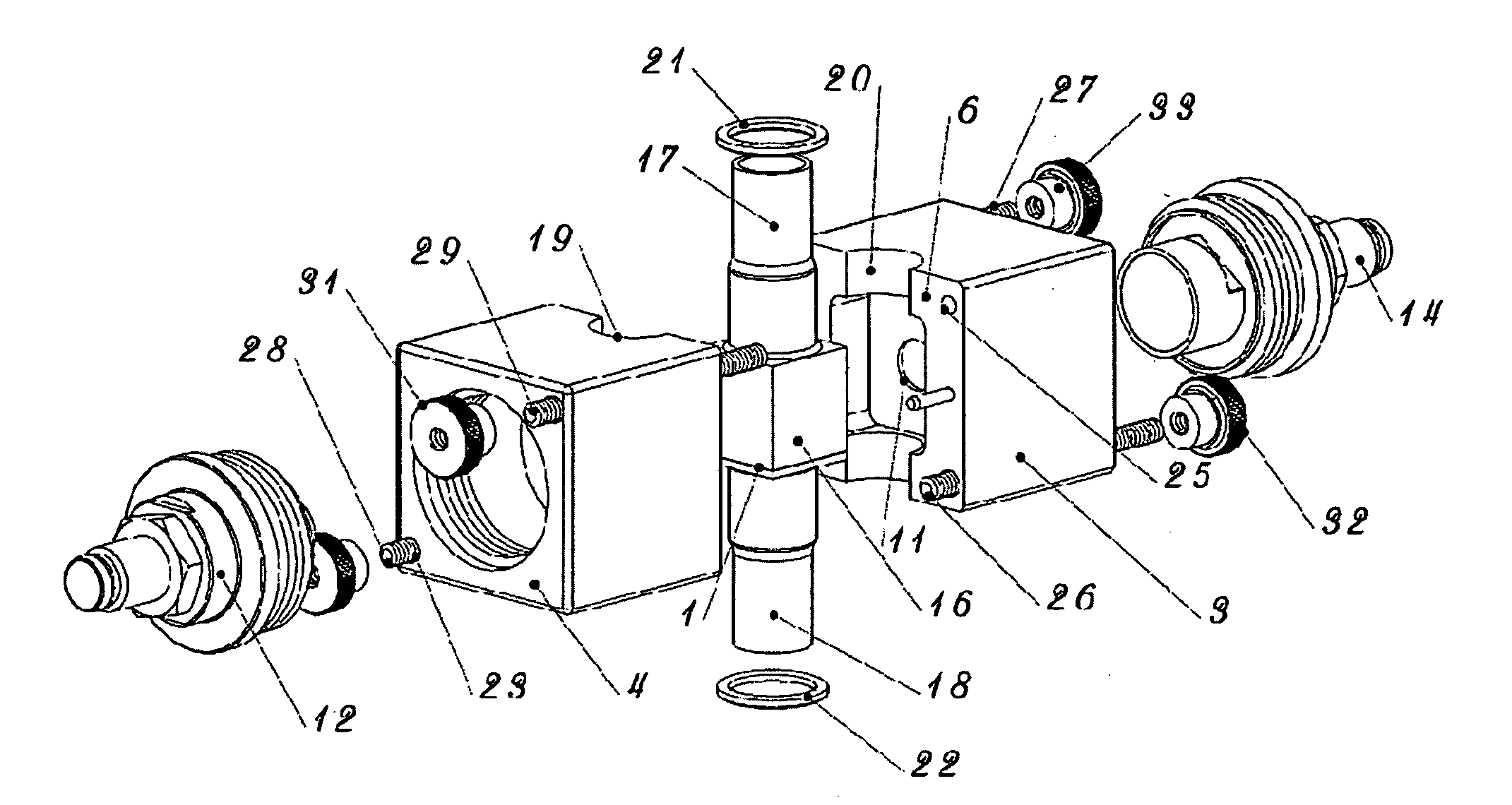
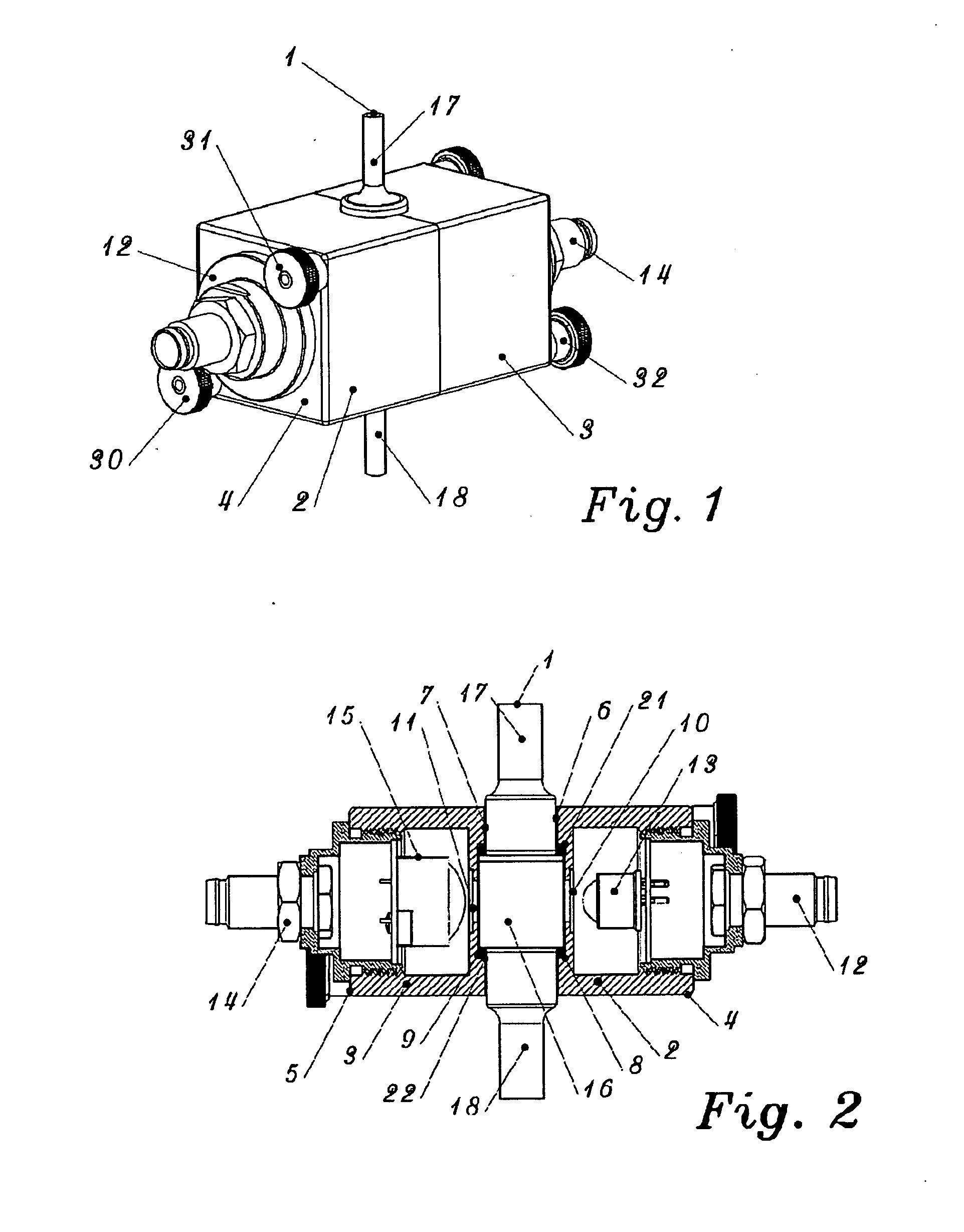
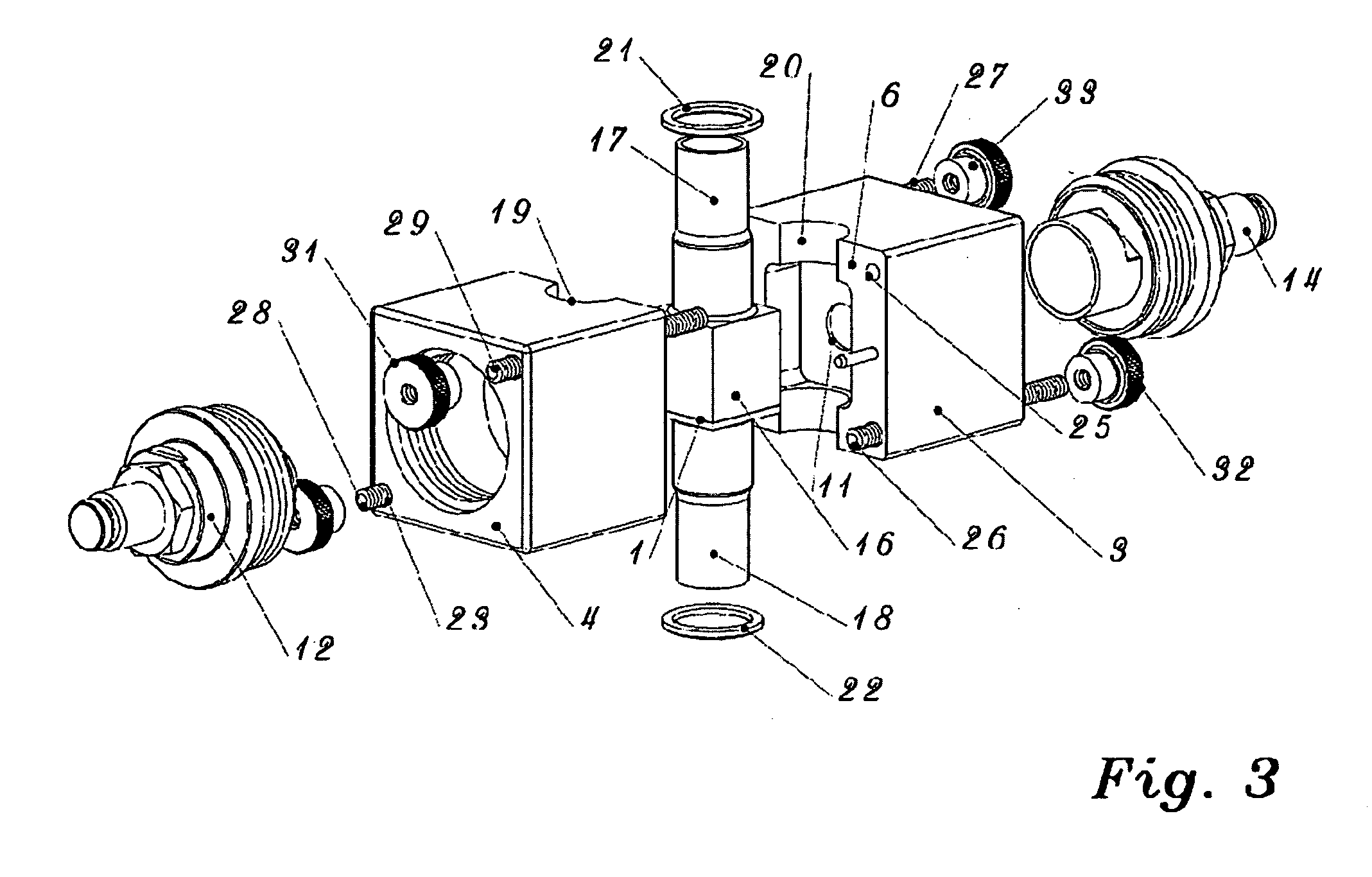
[0030]As illustrated in FIGS. 1 to 3 the optical sensor comprises a flow cell 1 which is accommodated in a housing comprising a first housing component 2 and a second housing component 3 of identical shape. Each housing component 2, 3 has a back end formed by a first end wall 4, 5. The first and second housing component 2, 3 have four side walls extending perpendicularly to the rectangular, in this example square, first end walls 4, 5. Opposite to the first end walls 4, 5 the housing components 2, 3 comprise second end walls 6, 7 in which a recess 8, 9 is formed. The second end walls 6, 7 each have a central aperture into which sapphire windows 10, 11 are sealed.

[0031]The sensor according to the exemplary embodiment of FIG. 1 to 3 has square end walls 4, 5. However, the end walls can be of any other shape, for example they can be circular. In this case, each housing component has only one tubular side wall, extending perpendicularly with respect to the circular end walls.

[0032]Into ...


PUM

PropertyMeasurementUnit
wavelength rangeaaaaaaaaaa
wavelengthaaaaaaaaaa
transparentaaaaaaaaaa

Abstract

An optical sensor is provided utilizing a disposable flow cell with a cell body, an inlet tube and an outlet tube providing a flow passageway extending between the inlet tube and the outlet tube through the cell body. The sensor comprises a first housing component comprising an open front end and a back end to which a removable light source is mounted and a second housing component comprising an open front end and a back end to which a light detector for detecting light emitted by the removable light source is mounted. The first and second housing components are detachably connected to one another, the open front ends of first and second housing components being tightly engaged to provide a sensor housing which accommodates and encloses the disposable flow cell. The light source and the detector are positioned at opposing sides of the cell body, an optical pathway extending along an axis between the light source and the detector through the cell body perpendicular to the flow passageway. The inlet tube and the outlet tube extend through apertures formed by corresponding recesses of the front ends of the first and the second housing component.

Description

FIELD OF INVENTION[0001]This invention pertains generally to inline sensors and measurements and, more particularly, to a sensor utilizing a disposable flow cell comprising a light source, e.g. a solid state emitter for use in optical inline measurements, e.g. for measuring optical absorbance in the ultra violet (UV) spectral range, and a detector.RELATED ART[0002]Inline optical measurements are used extensively in industrial applications, in particular in biotechnological and pharmaceutical applications. Known inline optical sensors comprise one or several light sources emitting a light beam of a certain wavelength range into a measuring cell, for example a flow cell carrying the medium to be monitored in a particular industrial application. Due to interaction with the medium optical effects like absorption, fluorescence or light scattering can occur. These effects can be used to determine a certain physical or chemical property of the medium to be monitored, such as for example th...

Claims


Application Information

Patent Timeline
Patent Type & Authority Applications(United States)
IPC IPC(8): G01J1/42G01N23/10
CPCG01N2021/0321G01N21/05
Inventor WYNN, WILLIAM H.
Owner ENDRESS HAUSER CONDUCTA GESELLSCHAFT FUER MESS UND REGELTECHNIK MBH CO KG
Why Eureka
Try Eureka