Aligning a lens with respect to an axis of beam propagation

a beam propagation and aligning technology, applied in the field of optics, can solve the problems of difficult strain relief of fiber from the mounting system, less than ideal applications such as fiber coupled lasers, and inability to remove fiber, so as to achieve precise optical alignment of collimating fiber bulkhead connectors, eliminate contamination worries, and improve the effect of optical alignmen

Inactive Publication Date: 2005-05-10
JDS UNIPHASE CORP
View PDF22 Cites 10 Cited by
  • Summary
  • Abstract
  • Description
  • Claims
  • Application Information

AI Technical Summary

Benefits of technology

[0022]Embodiments of the method and apparatus provide certain advantages over the prior art. For example they provide the degrees of freedom to accommodate typical manufacturing irregularities. They allow for extremely precise optical alignment of a collimating fiber bulkhead connector. They may provide a seal to eliminate contamination worries as the fiber is disconnected. They may also provide a “blast shield” for higher power fiber ends, should a fiber “burn” or outgas.

Problems solved by technology

There are many styles of fiber bulkhead design, however they each suffer from drawbacks that make them less than ideal for applications such as fiber coupled lasers.
Unfortunately the fiber is not removable.
Strain relieving the fiber from the mounting system becomes difficult and misalignment is a common problem.
Unfortunately, O-rings are not ideal for holding a micron-level tolerance over time, and this mount is known to drift and be highly imprecise.
This type of fiber mount needs to continuously be adjusted through its lifetime, making it an impractical solution for an OEM laser.
Although the fiber is removable, the very removal and replacement of the fiber will cause the mount to move, misaligning the system.
Unfortunately, such a design is expensive to implement.
Machining tolerances are exceptionally tight and fundamentally limit the precision of the system.
Off-the-shelf and low-volume solutions currently on the market are limited in their range of optics and coupling capabilities, and are typically low power solutions only.
It is impossible to achieve these tolerances with mechanical (i.e. bolts / snaps / references) fixturing alone.
Solder is occasionally used, but tends to creep or move as it solidifies, and continues to move as the residual stresses relieve themselves.
As such, methods that might creep, or retain residual stress are undesirable.
Plastics are also undesirable for long term stability.
In addition, many lasers and high-power optics are not meant to be “re-tweaked” into position once they have left the factory.
Most plastics and fixturing methods are not suitable, as they tend to outgas (and fog sensitive optics) causing failure.
Finally, most segments of the laser and high-power optics industry, such as the OEM solid-state laser industry, are not high-volume businesses.
A majority of the prior art fiber connections are not removable and most are not bulkhead connections.
In addition, most are not collimating solutions.
Furthermore, most are fiber to fiber only, which limits the use of the connector to coupling between two fibers having the same OD and / or same Numerical Aperture.
Cleanliness (outgassing) on a majority of the prior art would be prohibitive for higher powers and long term stability is highly questionable on most.
The fiber is aligned via a molded in or machined boss, which does not provide as precise an alignment as is often desired.
Furthermore, the apparatus does not truly seal, does not allow for alignment in X & Y, and is not designed for coupling light from one fiber to another.
In addition, the design is complex and predominately made using plastic.
Thus, there are many thermal expansion issues.
This is likely to damage coatings used in many laser and high-power optics applications.
This would not work for coupling fibers with different diameters or numerical apertures (NA) together.
This design does not allow for any Z-axis adjustment.
This would likely have a “spring back” force and be hard to calibrate.
In addition, this design requires an elaborate fixture and complex / precise machined parts.
Furthermore this design does not seal, is not removable, and is not a bulkhead connector.
In addition, this design uses solder, which is notorious for creep and strain.
The design also calls for a face-touching contact, which is bad for polished optical surfaces.
U.S. Pat. No. 4,925,265 describes an “Apparatus for Directing a Laser Beam into Optical Fibers.” Unfortunately, this design is not applicable for high power.
The fiber connector is not truly sealed.
Furthermore, the design does not facilitate easy alignment.
These connectors and methods are fiber to fiber only with no means of simple disconnection or reconnecting.
Such a design is not likely to work with different diameters or Numerical Apertures.
The connection is complex, which is not appropriate for small volume manufacturing.
The connection requires an index-matching fluid, which is incompatible with many high-power solutions.
This does not allow for coating or polishing the lens.
The lens is plastic, which is not compatible with many high-power applications.
The lens forming process limits surface quality.
The design does not allow for beam sampling between fiber faces and it is not clear whether the connection is disonnectable.
Furthermore, the solution is too complex for use with a single fiber.
Furthermore, this method does not provide for a bulkhead connector or repeatable insertion.
Since it is not necessary for a polarizer, the mount does not provide for translation of the polarizer along the Z-Axis and only allows the polarizer to rotate about the Z-Axis.
The required translational tolerances on such an optic are very coarse.
Furthermore, any alignment that they do provide would fall apart as soon as electrical power is removed.
The device is limited to mechanical level tolerances and it is not evident how this device continues to protect the optics when it is unplugged.
Published European Patent Application EP 1 195 630 A2 describes a “Fiber Optic Connector.” Although this device is sealed and removable it does not allow for alignment along the Z-Axis.
In addition the design does not facilitate polishing the connector ends.

Method used


Image

  • Aligning a lens with respect to an axis of beam propagation
  • Aligning a lens with respect to an axis of beam propagation
  • Aligning a lens with respect to an axis of beam propagation

Examples


Embodiment Construction

[0031]Although the following detailed description contains many specific details for the purposes of illustration, anyone of ordinary skill in the art will appreciate that many variations and alterations to the following details are within the scope of the invention. In the mathematical derivations described below certain assumptions have been made for the sake of clarity. These assumptions should not be construed as limitations on the invention. Accordingly, the exemplary embodiments of the invention described below are set forth without any loss of generality to, and without imposing limitations upon, the claimed invention.

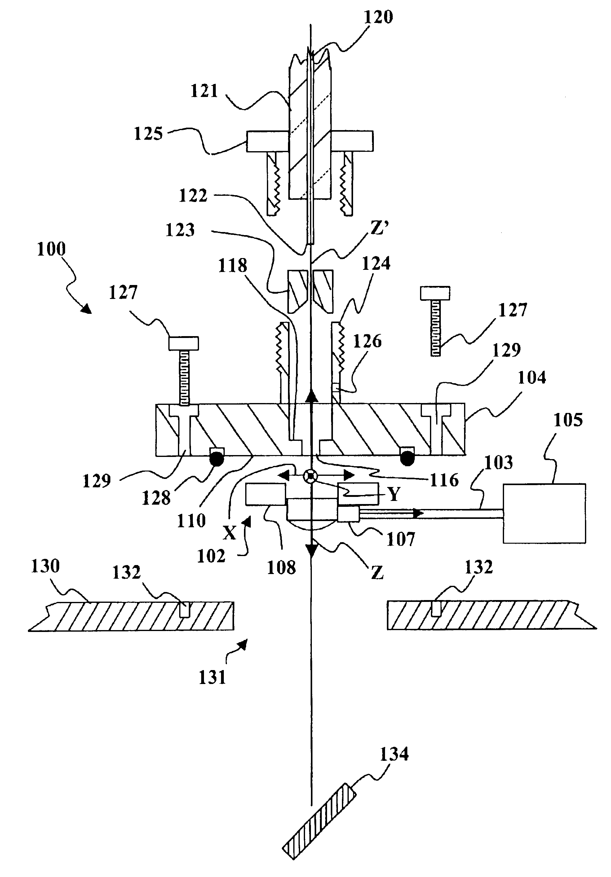
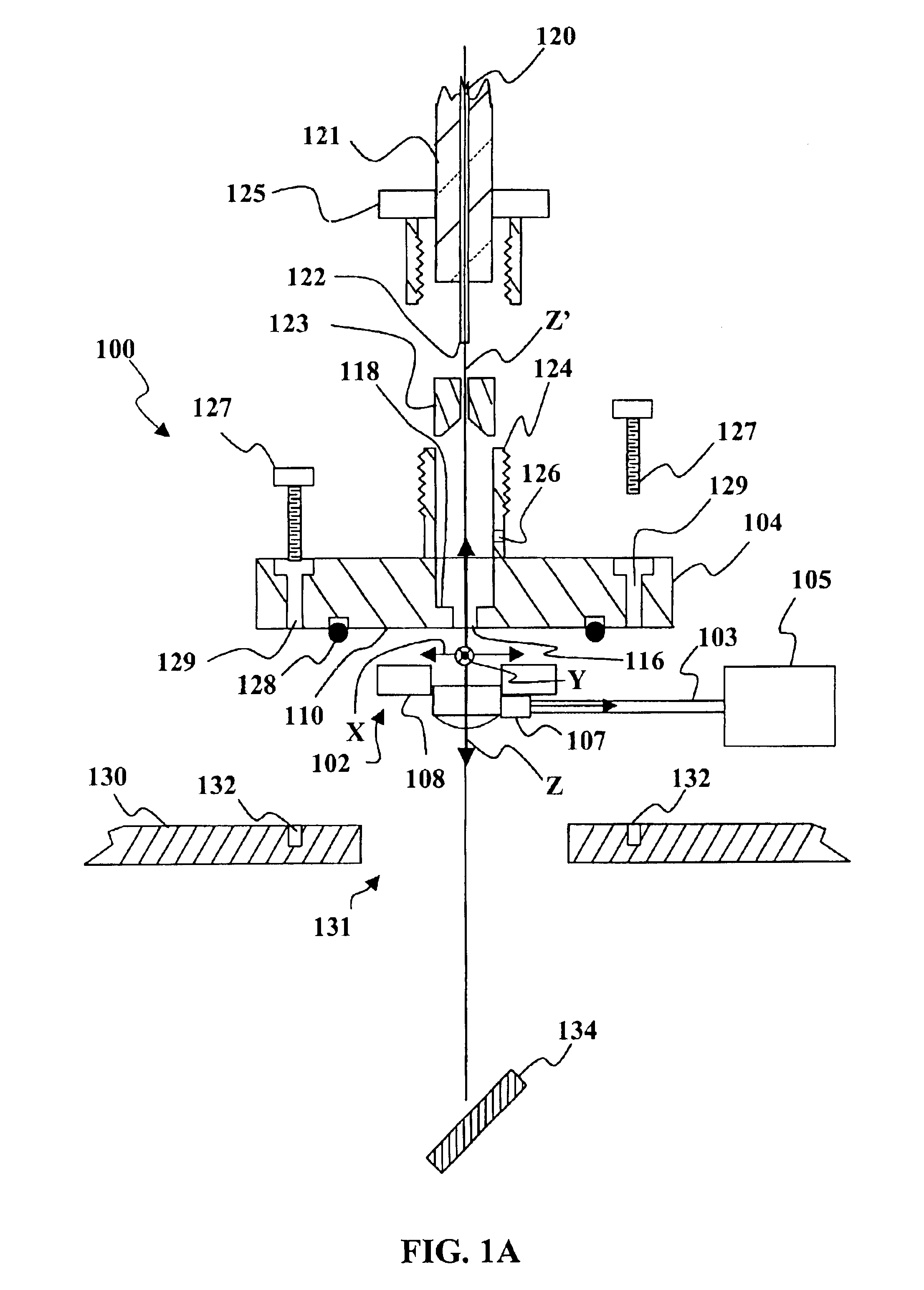
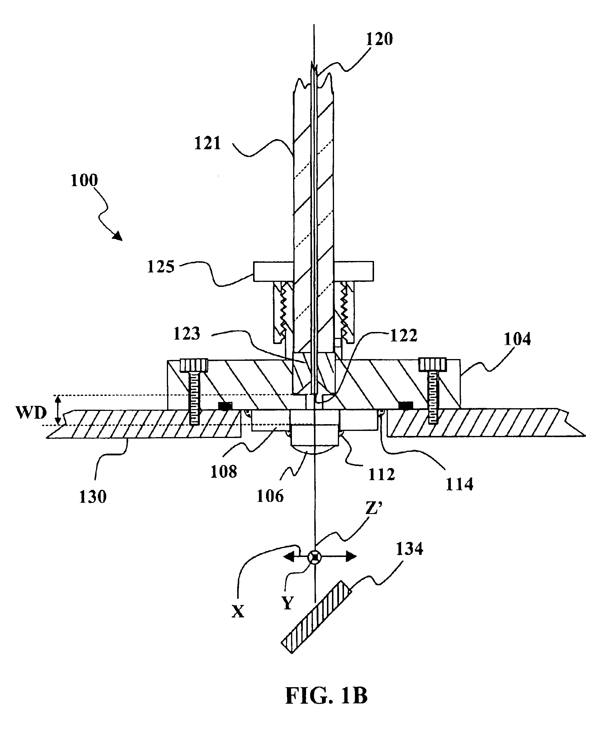
[0032]FIGS. 1A-1B depict an example of an apparatus 100 for aligning a lens with respect to a beam propagation axis. The apparatus includes a mount 102 and a bulkhead connector 104. The mount 102 and bulkhead connector 104 are configured to align an optic axis of the lens Z with the axis of beam propagation Z′. The axis of beam propagation Z′ may define a prefer...


PUM


Abstract

Methods and apparatus for aligning a lens with respect to an axis of beam propagation are disclosed. A position of the lens is adjusted with respect to the axis along one or more directions that lie substantially parallel to a surface of a bulkhead connector. The surface of the bulkhead connector is substantially not parallel to the axis of beam propagation. A position of the lens is adjusted along a direction substantially parallel to the axis of beam propagation. After adjustment, the position of the lens is fixed with respect to the surface. An example of a lens aligning apparatus includes a lens mount configured to receive the lens, a bulkhead connector having a surface, wherein the axis of beam propagation intersects a plane of the surface, means for fixing a position of the lens mount with respect to the surface; and means for fixing a position of the lens with respect to the lens mount.

Description

FIELD OF THE INVENTION[0001]This invention generally relates to optics and more particularly to aligning a lens with respect to an axis of beam propagation.BACKGROUND OF THE INVENTION[0002]Fiber bulkhead couplers are often used when coupling an optical fiber to an optical device. Such bulkhead couplers often include a collimating lens that must be aligned with respect to an axis of beam propagation to or from a fiber. There are many styles of fiber bulkhead design, however they each suffer from drawbacks that make them less than ideal for applications such as fiber coupled lasers. For example, in a pigtail coupler a fiber is coupled into a ferrule and held in place (typically inside of a sealed laser system). Unfortunately the fiber is not removable. Sealing around this design is typically a permanent adhesive solution. Strain relieving the fiber from the mounting system becomes difficult and misalignment is a common problem. Pigtail couplers typically require special handling and a...

Claims


Application Information

Patent Timeline
Patent Type & Authority Patents(United States)
IPC IPC(8): G01B11/27G02B6/32G02B6/38G02B6/42
CPCG01B11/272G02B6/4226G02B6/3816G02B6/32
Inventor BYER, MARK W.RICHARD, DEREK J.
Owner JDS UNIPHASE CORP
Why Eureka
Try Eureka