
Selective and oriented assembly of platelet materials and functional additives

a platelet material and functional additive technology, applied in the field of burnishing of optical effect flakes, can solve the problems of difficult control, limited control, and the operation does not lend itself to planar alignment of pigment flakes, and achieve the effect of improving optical performan

Inactive Publication Date: 2010-08-19
JDS UNIPHASE CORP
View PDF104 Cites 34 Cited by
  • Summary
  • Abstract
  • Description
  • Claims
  • Application Information

AI Technical Summary

Benefits of technology

[0014]In accordance with the invention, there is provided a method of conforming non-ductile flakes to a surface, comprising: coating at least a portion of the surface with a coating of adhesive or a paint; and, applying to the coating before the coating cures, a plurality of thin film flakes having a non-ductile insulating or semiconductor layer, wherein the thin-film flakes have a thickness of between 50 nm and 2,000 nm, and wherein the tin-film flakes have a length of between 2 microns and 200 microns; and, burnishing the plurality of thin-film flakes upon the surface so as to provide an active layer which conforms to the surface. Shaped flakes such as square, hexagonal, or other shaped flakes may also be used to promote coverage and enhanced optical performance.

Problems solved by technology

Unfortunately, some operations do not lend themselves to planar alignment of pigment flakes and others actually contribute to the degradation of alignment of flakes that are applied in a generally planar fashion.
Although this method works as intended, it does have some limitations.
However, in the method disclosed this is difficult to control for, other than ensuring that the flake loading is kept low enough.
Furthermore, flakes are generally controlled for by a magnetic field as described and may have some unwanted tilt.
Standard printing of non-ductile flakes or platelets in ink suffers from the deficiency of having a relatively high pigment loading which prevents optimum lay-down of the platelets upon printing and therefore prevents achievement of maximum chroma.
Standard printing results in multiple layers of flakes, with the lower layers not optically active and not providing value.

Method used


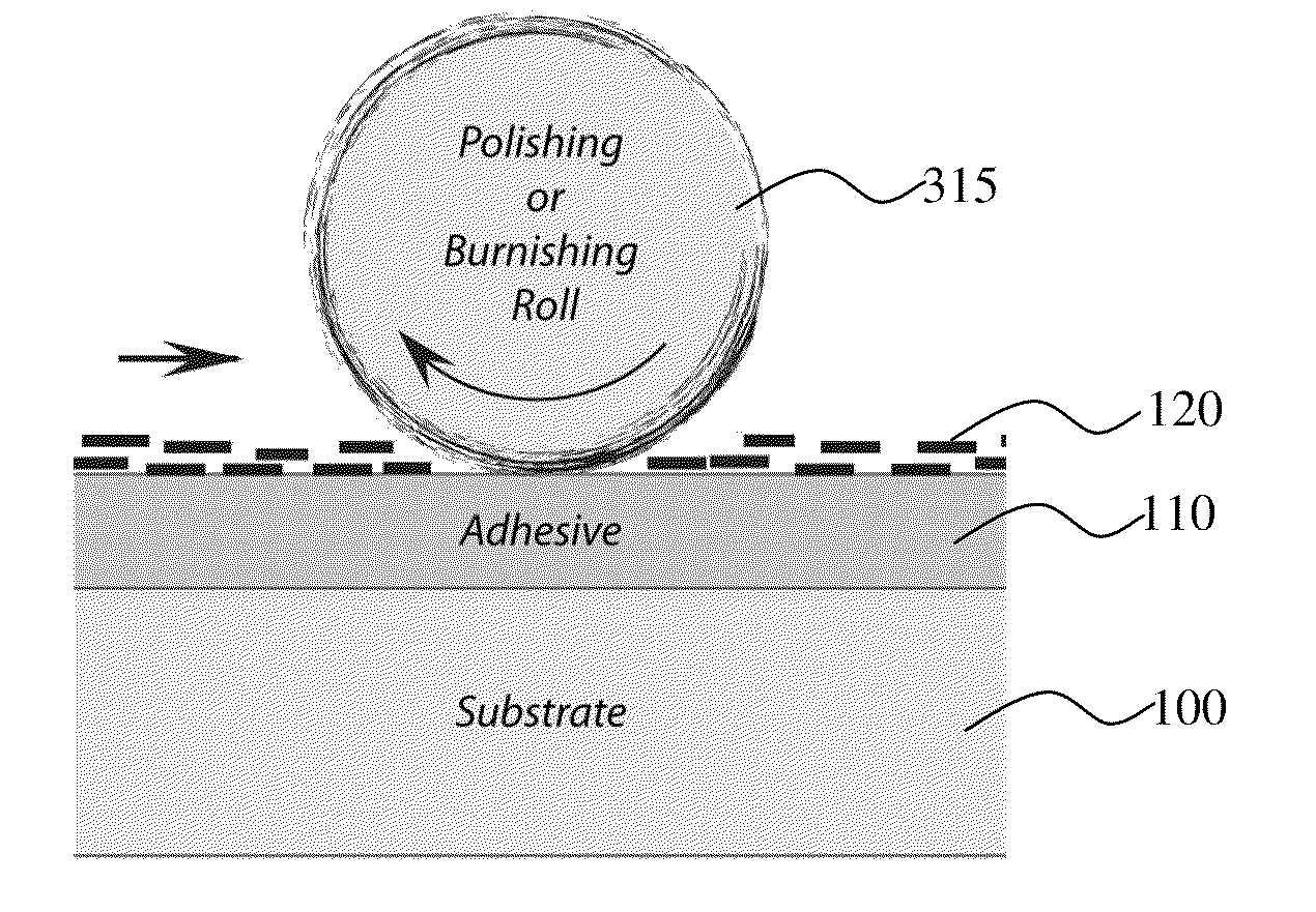
Image

  • Selective and oriented assembly of platelet materials and functional additives
  • Selective and oriented assembly of platelet materials and functional additives
  • Selective and oriented assembly of platelet materials and functional additives

Examples


Embodiment Construction

[0023]The term burnishing flakes used hereafter is to mean rubbing, polishing or brushing flakes so that they conform to the substrate upon which they are applied.

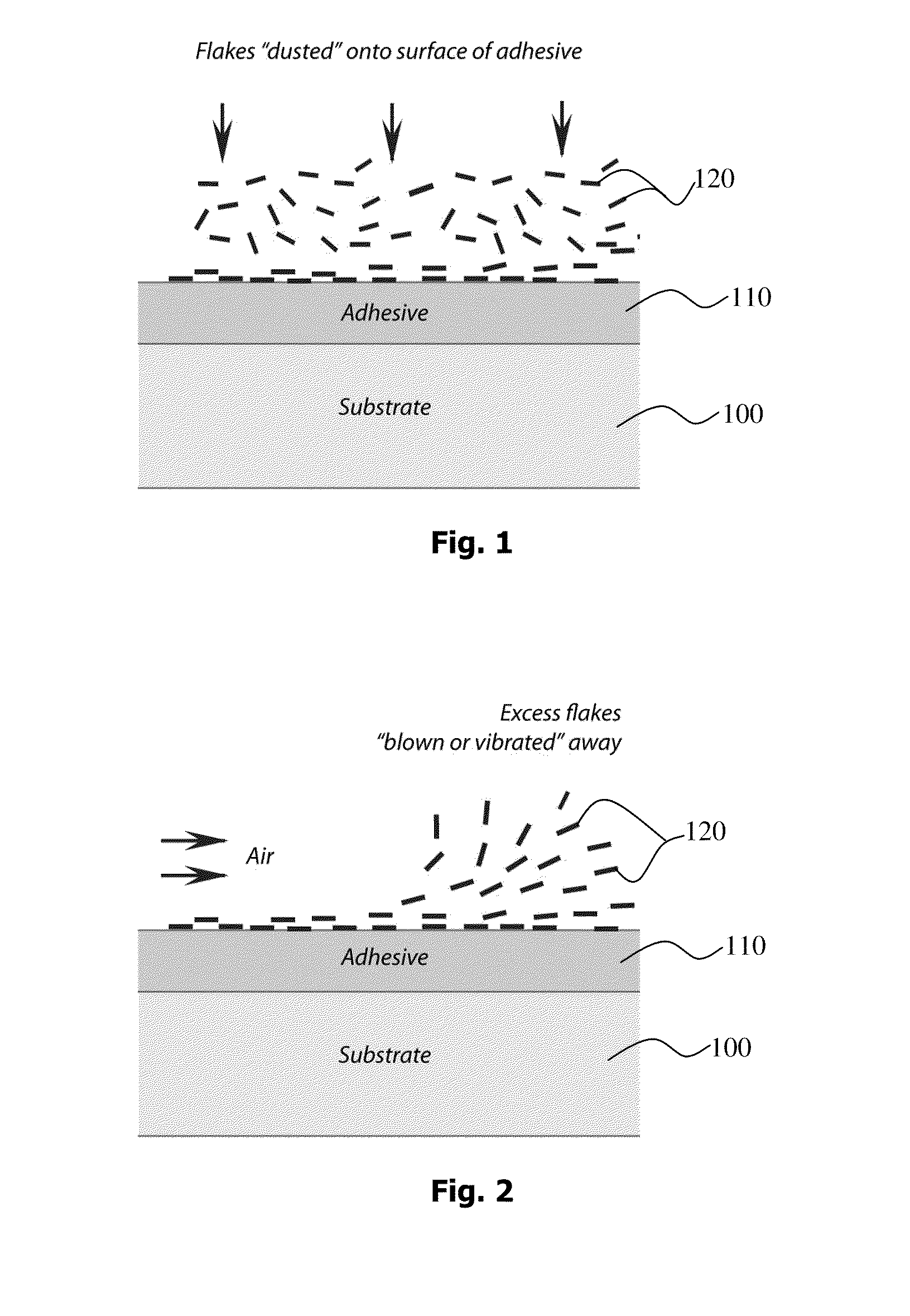
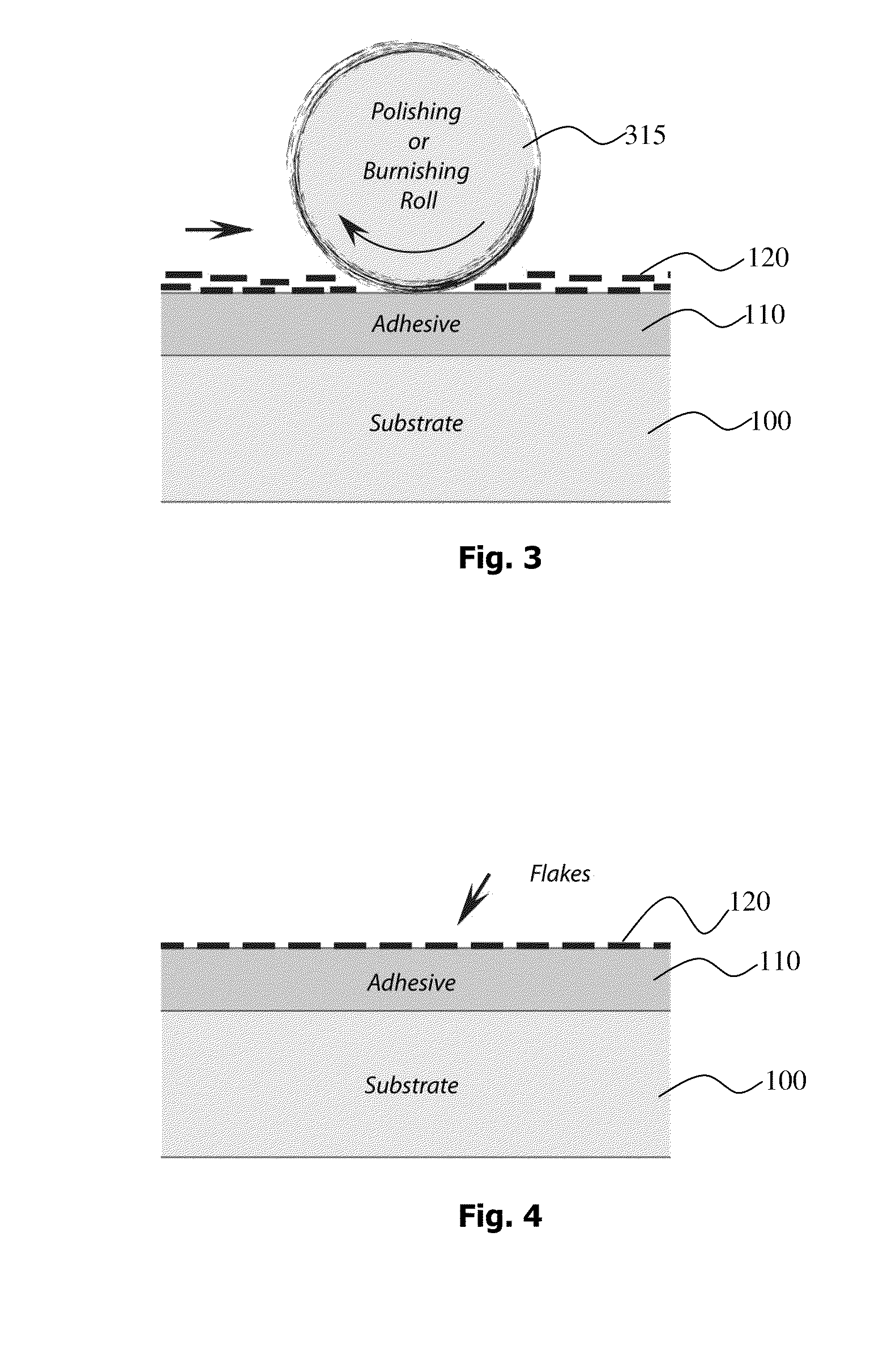
[0024]FIGS. 1 through 4 depict various stages of a process that provides a highly oriented specular layer of platelet form flakes upon a substrate which may be a web or an article to be coated. The article need not have a planar surface. For example, helmets, shoes, and other non-planar articles may be coated in this manner wherein the flakes conform to the surface.

[0025]Referring now to FIG. 1 substrate 100 supports an adhesive layer 110 coated on at least a portion of the substrate 100. Special effect flakes 120 having a layer of non-ductile material such as semiconductor or insulating material are dusted upon the adhesive layer. The adhesive layer may be applied to the entire substrate or may be applied to predetermined areas for example in a pattern such as a logo or forming other indicia. Craigcote 1029 was found to b...


PUM

PropertyMeasurementUnit
Lengthaaaaaaaaaa
Lengthaaaaaaaaaa
Lengthaaaaaaaaaa

Abstract

A method of conforming non-ductile flakes to a surface is provided wherein a surface is coated with the non-ductile flakes. A first step of coating at least a portion of the surface with a coating of adhesive or a paint is required and subsequently before the coating cures a plurality of thin film flakes having a non-ductile insulating or semiconductor layer are sprinkled upon the adhesive or paint while it is still tacky. Typically the thin-film flakes have a thickness of between 50 nm and 2,000 nm, and have a length of between 2 microns and 200 microns. The flakes having a non-ductile layer are then burnished upon the surface so as to provide an active layer, which conforms to the surface.

Description

CROSS-REFERENCE TO RELATED APPLICATION[0001]The present application is a continuation-in-part of U.S. patent application Ser. No. 11 / 278,600 filed Apr. 4, 2006, which claims priority from U.S. Provisional Patent Application Ser. No. 60 / 777,086 filed Feb. 27, 2006 and Ser. No. 60 / 668,852 filed Apr. 6, 2005, and is a continuation-in-part of U.S. patent application Ser. No. 11 / 313,165 filed Dec. 20, 2005, which is a continuation-in-part of U.S. patent application Ser. No. 11 / 022,106, filed Dec. 22, 2004, which is a continuation-in-part from U.S. patent application Ser. No. 10 / 386,894 filed Mar. 11, 2003, which claims priority from U.S. Provisional Patent Application Ser. No. 60 / 410,546 filed Sep. 13, 2002; from U.S. Provisional Patent Application Ser. No. 60 / 410,547 filed Sep. 13, 2002; from U.S. Provisional Patent Application Ser. No. 60 / 396,210 filed Jul. 15, 2002 by the disclosures of which are hereby incorporated in their entirety for all purposes; and U.S. patent application Ser. ...

Claims


Application Information

Patent Timeline
IPC IPC(8): G02B5/28B05D1/36B29C39/00B32B38/10B32B5/16
CPCB05D3/12B05D5/061B05D5/065B42D2035/20Y10T428/25G02B5/08G02B5/26G02B5/286G02B1/10B24B39/003B42D25/378
Inventor NOFI, MICHAEL R.LADEN, PATRICKMARKANTES, CHARLES T.KITTLER, JR., WILFRED C.COOMBS, PAUL G.
Owner JDS UNIPHASE CORP
Learn More