
Vein Authentication Apparatus, Imaging Apparatus for Vein Authentication, and Vein Illuminating Method

an imaging apparatus and authentication technology, applied in the field of vein authentication apparatus, can solve the problems of reducing the size and density of a portable communication device, affecting the authentication accuracy reducing the size of the incorporated apparatus, so as to achieve the effect of reducing the size and sufficiency of authentication accuracy

Inactive Publication Date: 2010-08-19
SONY CORP
View PDF32 Cites 13 Cited by
  • Summary
  • Abstract
  • Description
  • Claims
  • Application Information

AI Technical Summary

Benefits of technology

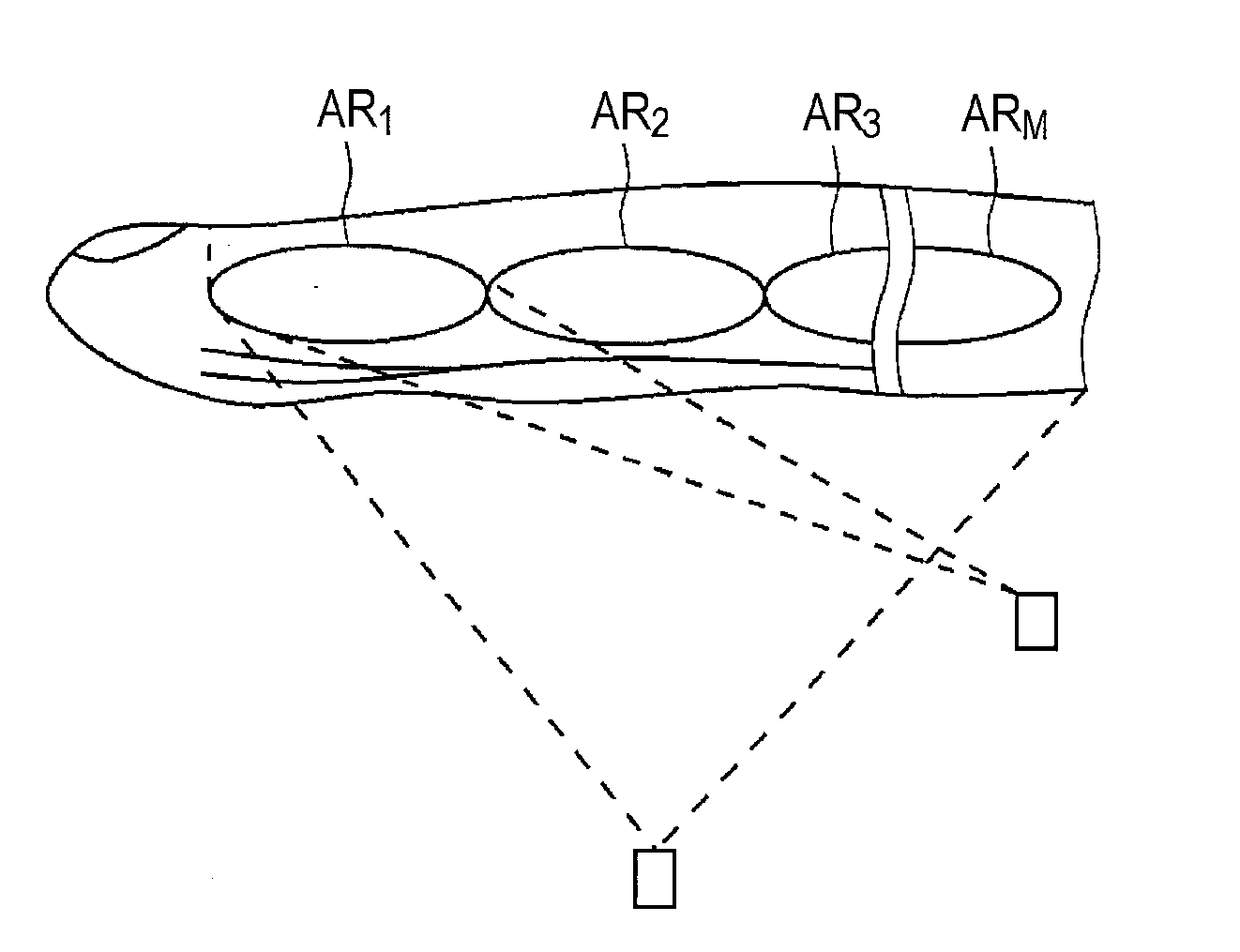
[0012]As described above, with the present invention, because an illuminating portion is controlled such that near-infrared light emitted from the illuminating portion is scattered behind a vein plexus opposite to an imaging section being in an imaging period among a plurality of imaging sections, and thus, the near-infrared light emitted from the illuminating portion can be permitted to enter a gap between an imaging section not being in an imaging period and the vein plexus, sufficient authentication accuracy is obtainable even if the illuminating portion is brought closer to an imaging target. Hence, size reduction can be achieved.

Problems solved by technology

Reduction in size and increase in density of a portable communication device in recent years are drastic, so size reduction in an incorporated apparatus is an important issue.
This may cause problems in which an authentication-target person feels uneasy about the finger being covered and the apparatus has a large size.
Because of this, there is a problem in which the apparatus has a large size.

Method used


Image

  • Vein Authentication Apparatus, Imaging Apparatus for Vein Authentication, and Vein Illuminating Method
  • Vein Authentication Apparatus, Imaging Apparatus for Vein Authentication, and Vein Illuminating Method
  • Vein Authentication Apparatus, Imaging Apparatus for Vein Authentication, and Vein Illuminating Method

Examples


Embodiment Construction

[0021]An embodiment in which the present invention is used is described below about the drawings.

(1) General Configuration of Authentication Apparatus

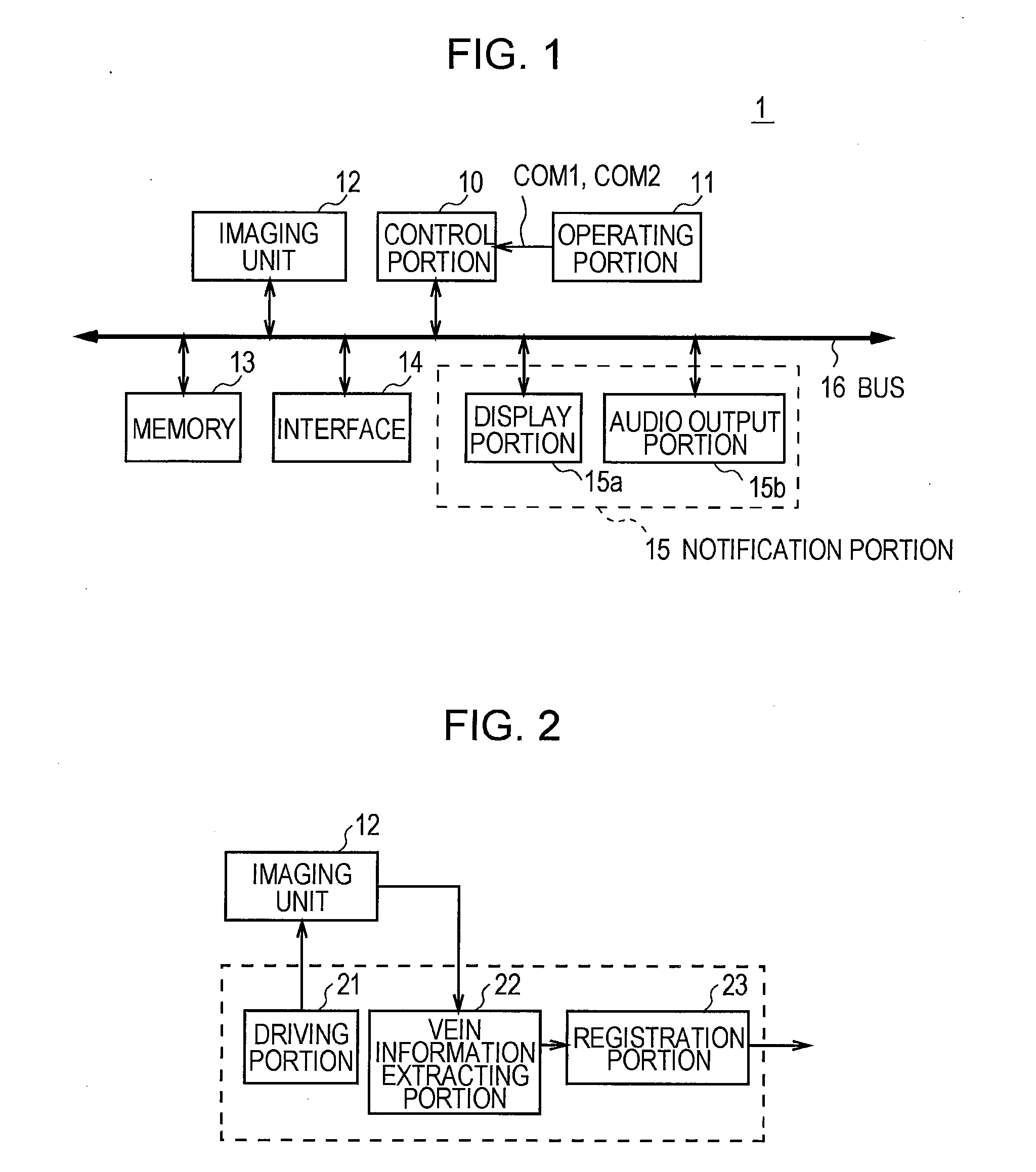
[0022]FIG. 1 illustrates a general configuration of an authentication apparatus 1 according to the present embodiment. This authentication apparatus 1 is configured such that an operating portion 11, an imaging unit 12, a memory 13, an interface 14, and a notification portion 15 are connected to a control portion 10 through a bus 16.

[0023]The control portion 10 is configured as a computer containing a central processing unit (CPU) controlling the whole of the authentication apparatus 1, a read-only memory (ROM) in which various programs and setting information are stored, and a random-access memory (RAM) serving as a work memory of the CPU.

[0024]In response to a user operation, a command COM1 for a mode for registering a vein of a finger of a user being a registration target (hereinafter, the mode is referred to as a blood-vessel regis...


PUM


Abstract

An imaging apparatus capable of expanding a range for use in acquiring a good-quality image, an authentication apparatus, and a light-source driving method are provided. The authentication apparatus includes an imaging portion including a plurality of imaging sections for imaging reflected light reflected from a vein plexus inside a finger and transmitted light transmitted through the vein plexus, the imaging portion being controlled such that the imaging sections perform imaging in different periods, an illuminating portion arranged on the same direction side as the imaging portion and configured to illuminate the vein plexus with near-infrared light, an authentication processing portion configured to perform authentication processing on the basis of an image imaged by the imaging portion and vein information previously stored, and an illumination control portion configured to control the illuminating portion such that the near-infrared light emitted from the illuminating portion is scattered behind a vein section corresponding to an imaging section being in an imaging period among the plurality of imaging sections.

Description

TECHNICAL FIELD[0001]The present invention relates to a vein authentication apparatus, an imaging apparatus for vein authentication, and a vein illuminating method.BACKGROUND ART[0002]Authentication technologies utilizing a living body as authentication means are coming into wide use. And, incorporating biometric authentication into a potable communication device, such as a cellular phone, enables authentication processing to be easily performed on a communication party anywhere through the portable communication device, so it is important to incorporate a biometric authentication apparatus into a portable communication device. Reduction in size and increase in density of a portable communication device in recent years are drastic, so size reduction in an incorporated apparatus is an important issue.[0003]Traditionally, there are vein authentication apparatuses utilizing a vein as a target, and one example of such vein authentication apparatuses is a vein authentication apparatus ca...

Claims


Application Information

Patent Timeline
Patent Type & Authority Applications(United States)
IPC IPC(8): G06K9/00
CPCG06K9/00885G06K9/00107G06K2009/00932G06V40/1382G06V40/10G06V40/14
Inventor SATO, HIDEO
Owner SONY CORP
Learn More