Image profile analysis (IPA) method for pm fiber alignment

Inactive Publication Date: 2010-08-19
AFL COMM LLC
View PDF6 Cites 18 Cited by
  • Summary
  • Abstract
  • Description
  • Claims
  • Application Information

AI Technical Summary

Benefits of technology

[0020]Exemplary embodiments of the present invention provide a method of aligning a polarization-maintaining optical fiber.
[0021]According to an aspect of the present invention, there is provided a method of analyzing a polarization-maintaining optical fiber. The method includes illuminating a side of the optical fiber; rotating the optical fiber at incremental rotation angles; obtaining an image profile of the optical fiber at each rotation angle such that a focal plane of the image profile is positioned within the optical fiber; measuring an image parameter at each rotation angle based on the respective image profile; and constructing a measured image parameter profile of the optical fiber as a function of rotation angle based on the measured image parameters. The method may also include constructing an approximated image parameter profile of the optical fiber as a function of rotation angle by curve-fitting a mathematical function to the measured image parameter profile. The image parameter may be an upper ridge intensity difference, a lower ridge intensity difference, an upper valley intensity difference, a lower valley intensity difference, or a central peak intensity. The mathematical function may be a truncated Fourier series. The method may also include selecting a desired rotation angle based on the approximated image parameter profile and rotating the optical fiber to the desired rotation angle. The desired rotation angle may be along the slow axis or the fast axis of the optical fiber.
[0022]According to another aspect of the present invention, there is provided a method of aligning a polarization-maintaining optical fiber that includes illuminating a side of a reference optical fiber; rotating the reference optical fiber at incremental rotation angles; obtaining a reference image profile of the reference optical fiber at each rotation angle such that a focal plane of the reference image profile is positioned within the reference optical fiber; measuring an image parameter of the reference optical fiber at each rotation angle based on the respective reference image profile; constructing a measured image parameter profile of the reference optical fiber as a function of rotation angle based on the measured image parameters of the reference optical fiber; constructing an approximated image parameter profile of the reference optical fiber as a function of rotation angle by curve-fitting a mathematical function to the measured image parameter profile of the reference optical fiber; illuminating a side of the polarization-maintaining optical fiber; rotating the polarization-maintaining optical fiber at incremental rotation angles; obtaining an image profile of the polarization-maintaining optical fiber at each rotation angle such that a focal plane of the polarization-maintaining image profile is positioned within the polarization-maintaining optical fiber; measuring an image parameter of the polarization-main

Problems solved by technology

bers. Therefore, some of the optical power in the preferred polarization axis (most commonly the slow axis) may be lost and cross over to the other polarization
However, this manual alignment method has the disadvantages of being time-consuming and operator-dependent.
One disadvantage of the POL method is that because the focal plane (170) is outside of the polarization-maintaining optical fiber (160), the POL method is limited to analyzing data from the exemplary contrast profiles illustrated in FIGS. 9A-9C, which are measured from images similar to the image shown in FIG. 7.
The POL contrast profile may not provide adequate data to enable alignment of some types of polarization maintaining fiber.
Even if the POL contrast profile provides sufficient data for fiber alignment, the POL method may not provide sufficient accuracy for aligning the polarization-maintaining optical fiber.
The PAS method is limited to aligning polarization-maintaining optical fibers that have very distinct image profiles that exhibit symmetry from the center of the fiber when either the slow or fast axis of the fiber is observed in the plane of t

Method used


Image

  • Image profile analysis (IPA) method for pm fiber alignment
  • Image profile analysis (IPA) method for pm fiber alignment
  • Image profile analysis (IPA) method for pm fiber alignment

Examples


Embodiment Construction

[0056]The present invention will now be described more fully with reference to the accompanying drawings, in which exemplary embodiments of the invention are shown. These embodiments are provided so that this disclosure will be thorough and complete, and will fully convey the concept of the invention to those skilled in the art. However, the invention may be embodied in many different forms, and should not be construed as being limited to the exemplary embodiments set forth herein. In the drawings, like reference numerals denote like elements, and the thicknesses of layers and regions may be exaggerated for clarity and convenience.

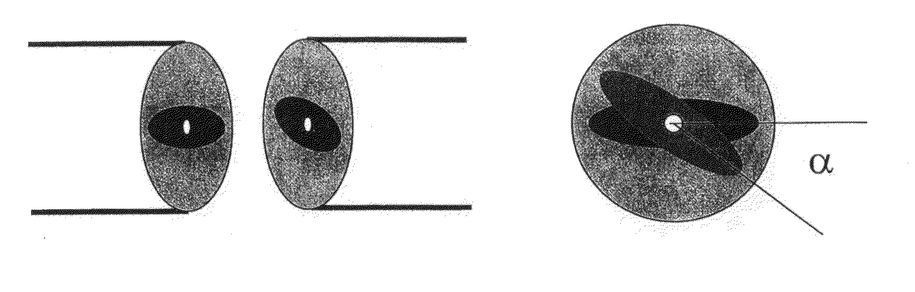
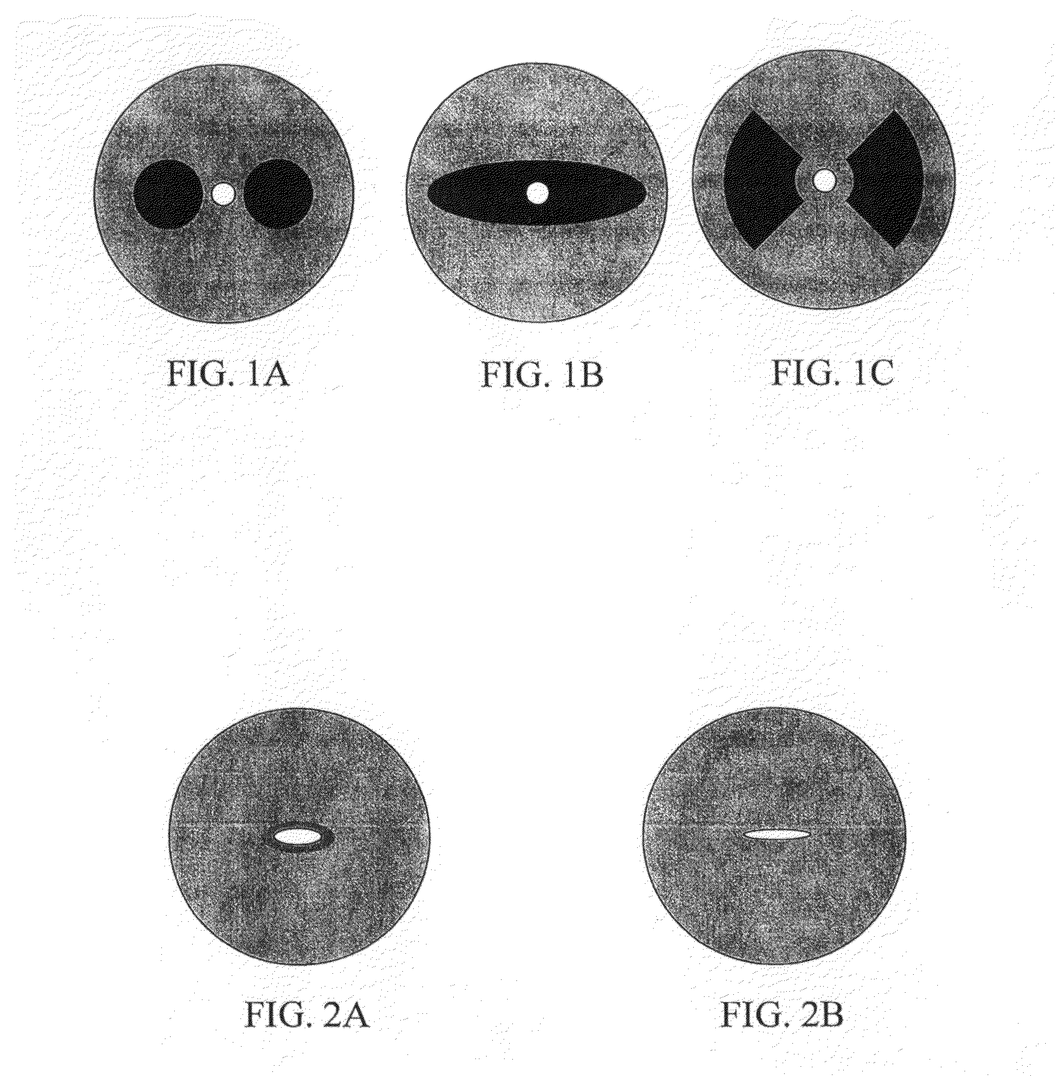
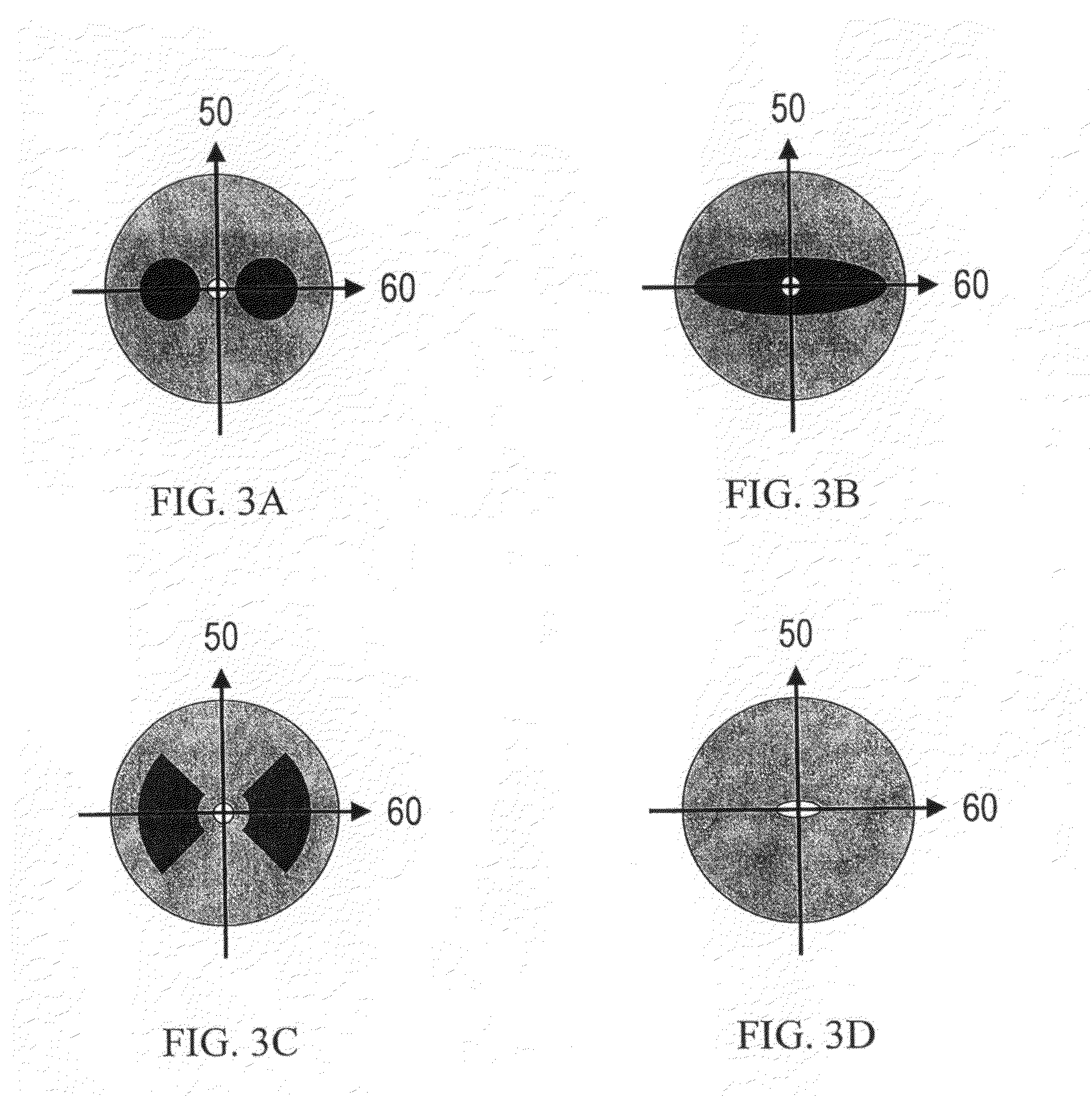
[0057]According to an exemplary embodiment of the present invention, a method for aligning a polarization-maintaining optical fiber is provided. FIG. 12 shows image profiles of ends of two polarization-maintaining optical fibers. Each of the image profiles is acquired by using the method shown in FIG. 10, in which collimated light is incident on the side o...


PUM


Abstract

A method of aligning a polarization-maintaining optical fiber by image profile analysis is provided. The method of aligning a polarization-maintaining optical fiber may include analyzing the polarization-maintaining optical fiber by illuminating a side of the optical fiber; rotating the optical fiber at incremental rotation angles; obtaining an image profile of the optical fiber at each rotation angle such that a focal plane of the image profile is positioned within the optical fiber; measuring an image parameter at each rotation angle based on the respective image profile; and constructing a measured image parameter profile of the optical fiber as a function of rotation angle based on the measured image parameters. The method may also include constructing an approximated image parameter profile of the optical fiber as a function of rotation angle by curve-fitting a mathematical function to the measured image parameter profile.

Description

CROSS-REFERENCE TO RELATED PATENT APPLICATION[0001]This application claims the benefit of U.S. Provisional Application No. 61 / 101,852, filed on Oct. 1, 2008 in the United States Patent and Trademark Office, the disclosure of which is incorporated by reference in its entirety.BACKGROUND OF THE INVENTION[0002]1. Field of the Invention[0003]Methods consistent with the present invention relate to aligning a polarization-maintaining optical fiber, and more particularly, to aligning a polarization-maintaining optical fiber by image profile analysis.[0004]2. Description of the Related Art[0005]Polarization-maintaining optical fiber is a type of optical fiber in which the polarization of linearly-polarized light is maintained during propagation through the optical fiber. One type of polarization-maintaining optical fiber induces stress in the core by using a cladding with a non-circular cross-section or rods of another material within the cladding. For example, FIG. 1A shows a cross-section...

Claims


Application Information

Patent Timeline
IPC IPC(8): G02B6/26G06K9/00G01N21/00
CPCG02B6/2555
Inventor ZHENG, WENXINDUKE, DOUGKUBO, TOSHIKIMALINSKI, BRYAN
Owner AFL COMM LLC
Why Eureka
Try Eureka