Fuel cell and fuel cell stack comprising the same
a fuel cell and stack technology, applied in the direction of cell components, electrochemical generators, cell component details, etc., can solve the problems of deterioration of the membrane, insufficient reaction of the above reaction in the upstream portion of the reactant gas channel, etc., and achieve the effect of suppressing the degradation of the electrolyte layer
- Summary
- Abstract
- Description
- Claims
- Application Information
AI Technical Summary
Benefits of technology
Problems solved by technology
Method used
Image
Examples
embodiment 1
Configuration of Fuel Cell Stack
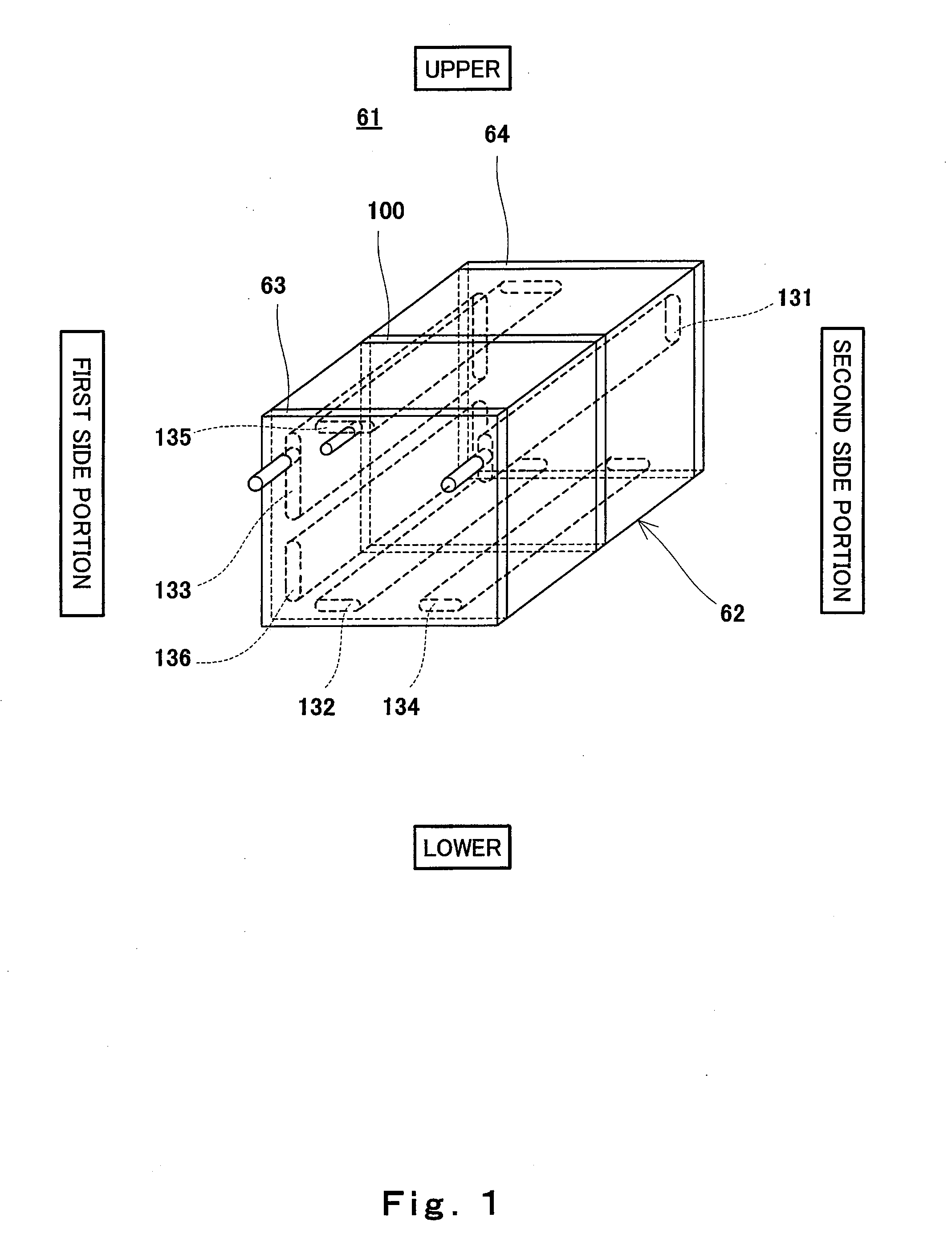
[0072]FIG. 1 is a perspective view schematically showing an exemplary configuration of a fuel cell stack according to Embodiment 1 of the present disclosure. In FIG. 1, the upper and lower sides of the fuel cell stack are expressed as the upper and lower sides in FIG. 1.
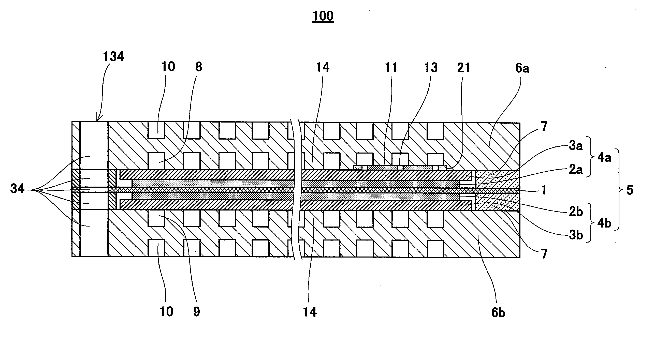
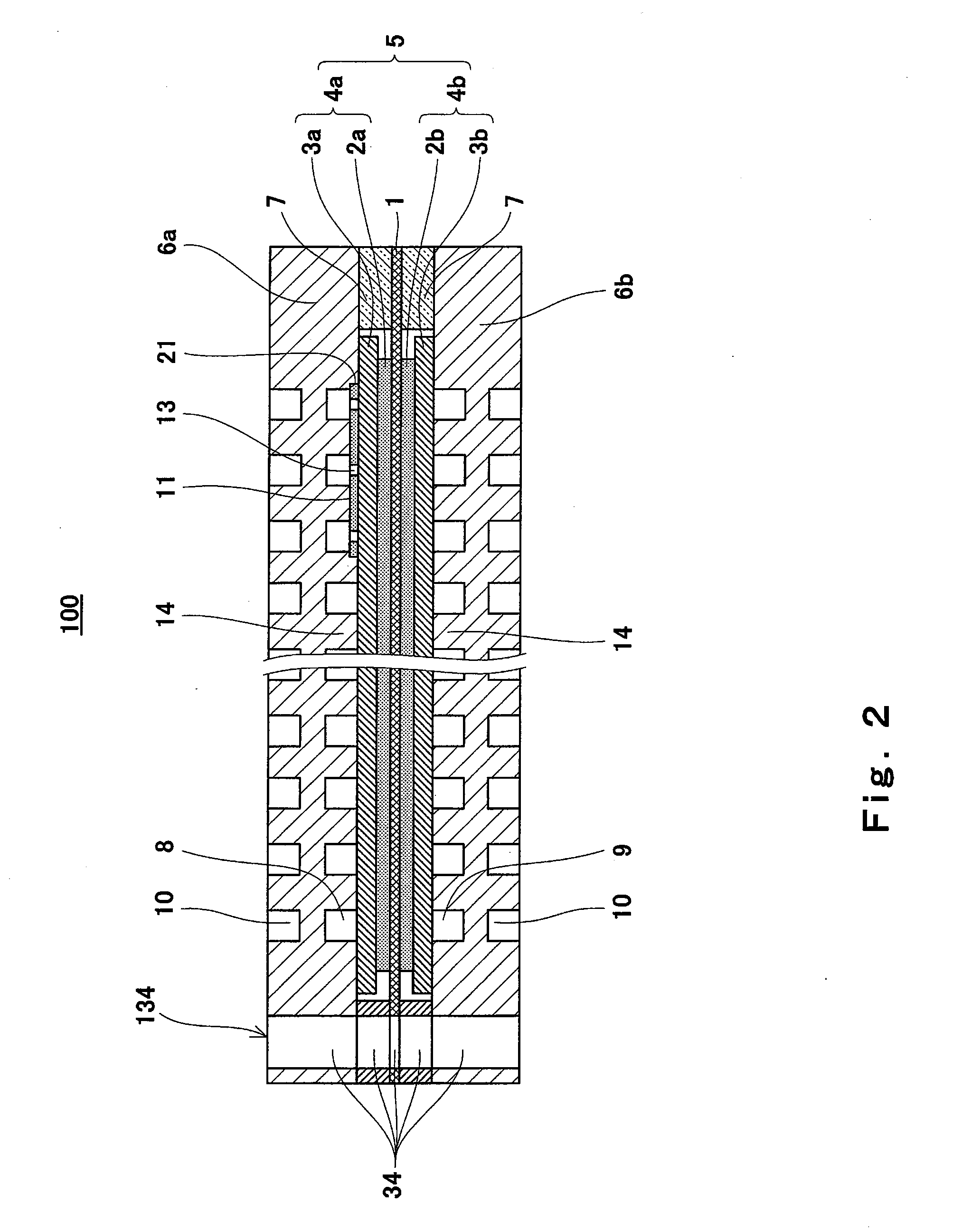
[0073]As shown in FIG. 1, a fuel cell stack 61 according to Embodiment 1 of the present disclosure includes a cell stack body 62 composed of polymer electrolyte fuel cells 100 (hereinafter simply referred to as fuel cells) which have a plate shape as a whole and are stacked together in a thickness direction thereof, first and second end plates 63 and 64 disposed at both ends of the cell stack body 62, and fastener members (not shown) fastening the cell stack body 62 to the first and second end plates 63 and 64, in a direction in which fuel cells 100 are stacked together. Although current collectors and insulating plates are provided at the first and second end plates 63 and 64, they ar...
embodiment 2
[0151]FIG. 8 is a schematic view showing an exemplary configuration of the inner surface of a cathode separator of a fuel cell stack according to Embodiment 2 of the present disclosure. FIG. 9 is a schematic view showing an exemplary configuration of the inner surface of an anode separator of the fuel cell stack according to Embodiment 2 of the present disclosure. In FIG. 8, the upper and lower sides of the cathode separator are expressed as the upper and lower sides in FIG. 8 and a part of the fuel gas channel is indicated by imaginary lines. In FIG. 9, the upper and lower sides of the anode separator are expressed as the upper and lower sides in FIG. 9 and a part of the oxidizing gas channel is indicated by imaginary lines.
[0152]Referring to FIGS. 8 and 9, the fuel cell stack 61 (fuel cell 100) according to Embodiment 2 of the present disclosure has a configuration which is basically identical to that of the fuel cell stack 61 (fuel cell 100) of Embodiment 1 but is different from ...
embodiment 3
[0164]FIG. 10 is a schematic view showing an exemplary configuration of a cathode separator of a fuel cell stack (fuel cell) according to Embodiment 3 of the present disclosure. FIG. 11 is a schematic view showing an exemplary configuration of an anode separator of the fuel cell stack (fuel cell) according to Embodiment 3 of the present disclosure. In FIG. 10, the upper and lower sides of the cathode separator are expressed as the upper and lower sides in FIG. 10 and a part of the fuel gas channel is indicated by imaginary lines. In FIG. 11, the upper and lower sides of the anode separator are expressed as the upper and lower sides in FIG. 11 and a part of the oxidizing gas channel is indicated by imaginary lines.
[0165]Referring to FIGS. 10 and 11, the fuel cell stack 61 (fuel cell 100) according to Embodiment 3 of the present disclosure has a configuration which is basically identical to those of the fuel cell stacks 61 (fuel cells 100) of Embodiment 1 an Embodiment 2 but is differ...
PUM
 Abstract
Description
Claims
Application Information
 - R&D Engineer
- R&D Manager
- IP Professional
- Industry Leading Data Capabilities
- Powerful AI technology
- Patent DNA Extraction
Browse by: Latest US Patents, China's latest patents, Technical Efficacy Thesaurus, Application Domain, Technology Topic.
© 2024 PatSnap. All rights reserved.Legal|Privacy policy|Modern Slavery Act Transparency Statement|Sitemap


