
Intravenous catheter insertion and blood sample devices and method of use

Active Publication Date: 2010-08-19
VASCULAR PATHWAYS
View PDF35 Cites 153 Cited by
  • Summary
  • Abstract
  • Description
  • Claims
  • Application Information

AI Technical Summary

Benefits of technology

[0012]In one aspect, the intravenous catheter insertion device has an interior space is dimensioned to store the access needle and the guide wire after use. In one configuration the intravenous catheter insertion device, a distal end of the guide wire is visible in the housing after use. In one alternative, a view port or window is provided in the housing that permits inspection of the guide wire tip. In one configuration, operation of the catheter advancement device is initiated by a user. In other aspects, an insertion resistance detector adapted to monitor the operation of the catheter advancement device and / or a guide wire insertion device, depending upon device configuration. In one configuration of an intravenous catheter insertion device there is a notch in the housing shaped to prevent the withdrawal of the guide wire or needle into the housing. In a variation of this configuration, the intravenous catheter insertion device includes a by pass around the notch in the housing that allows the withdrawal of the guide wire or needle into the housing. In still other configurations, the intravenous catheter insertion device has a stop within the housing shaped to prevent the withdrawal of the guide wire tip into the housing and facilitate inspection of the guide wire tip.
[0019]In another aspect of the blood draw device, the seal is configured to form a seal around the guide wire when the guide wire is in the first interior volume portion and the access needle is completely within the second interior volume portion. In another aspect, the seal is configured to form a seal around the access needle while the access needle is within the first interior volume portion. In another aspect, the seal partitions the interior volume so as to substantially separate the first interior volume portion from the second interior volume portion. In another aspect, the seal partitions the interior volume but allows communication between the first interior volume portion and the second interior volume portion.

Problems solved by technology

Catheter insertion and blood collection are two activities that are often made more difficult in patients with small or collapsed vessels or with other conditions that complicate insertion of a device into the patient's vessels.

Method used


Image

  • Intravenous catheter insertion and blood sample devices and method of use
  • Intravenous catheter insertion and blood sample devices and method of use
  • Intravenous catheter insertion and blood sample devices and method of use

Examples


Embodiment Construction

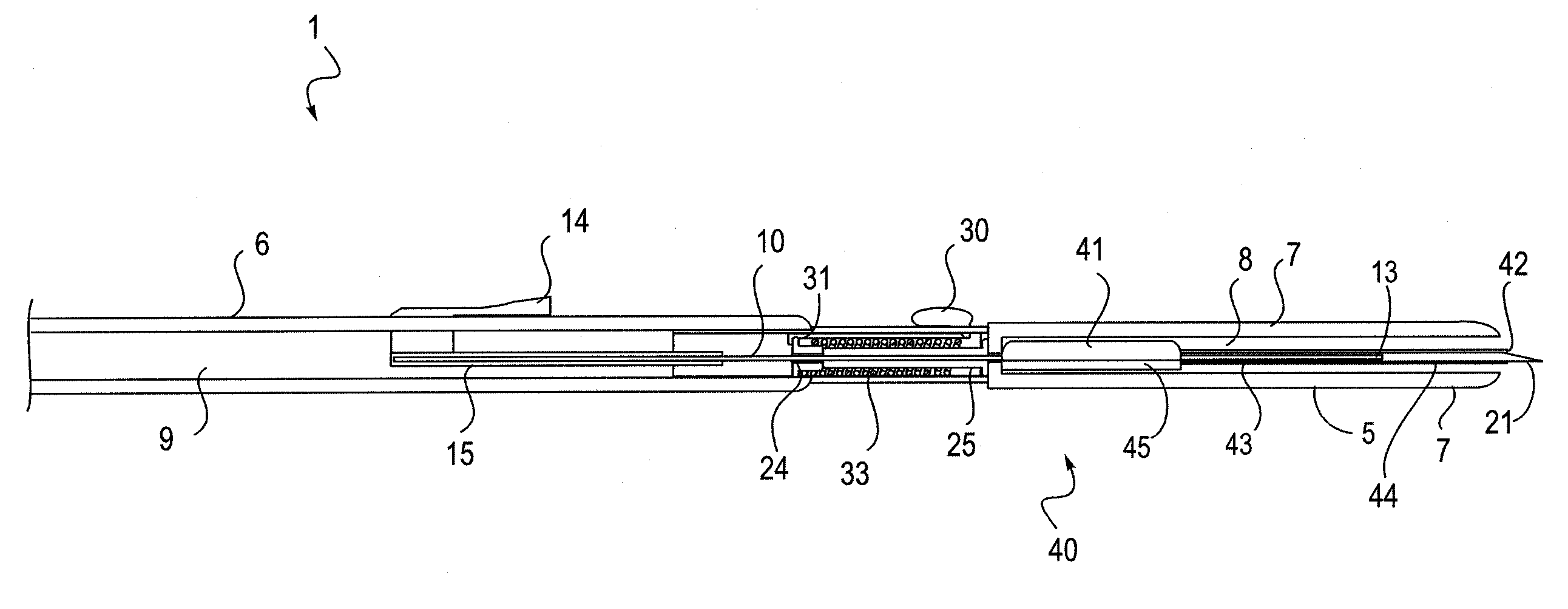
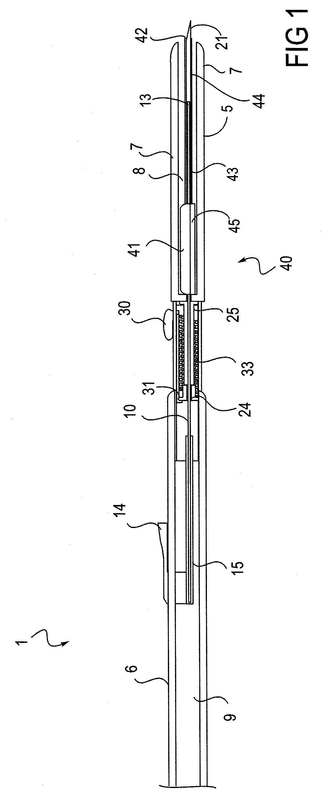
[0074]FIG. 1 shows a section view of an intravenous catheter insertion device 1 according to one embodiment the present invention. Insertion device 1 includes an insertion device housing 5 having a proximal end 6, a distal end 7 and an interior space 9. A slot 8 is provided in the distal end 7 to allow movement of the catheter hub 45 along the interior space 9. The guide wire 10 has a distal end 11, a proximal end 12 and a guide wire tip 13. The guide wire tip 13 may be straight, coiled, curved or in any of a number of shapes to allow for atraumatic insertion into and translation along a vessel. There is also a guide wire advancement lever 14 and a guide wire carrier 15. The guide wire 10 is attached to the guide wire carrier 15 and moveable relative using the guide wire advancement level 14. There is also an access needle 20 having a distal end 21, a proximal end 22 and an access needle lumen 23. The access needle 20 is contained within a needle carrier 25. The needle carrier inclu...


PUM


Abstract

Devices and methods for guidewire assisted placement of catheters into blood vessels are described. Some of the devices and methods relate to automated or partially automated or assisted insertion and placement of an intravenous catheter into a vein or artery of a patient. Other of the devices are blood draw devices and methods for insertion and placement of an intravenous device into a vein or artery of a patient or to withdraw a blood sample from the patient. The devices also provide for guide wire tip inspection after use.

Description

CROSS REFERENCE TO RELATED APPLICATIONS[0001]This application claims the benefit of priority to U.S. Provisional Patent Application No. 60 / 916,552 filed on May 7, 2007, entitled “Intravenous Catheter Insertion and Blood Sample Devices and Method of Use” and U.S. Provisional Patent Application No. 60 / 916,553 filed on May 7, 2007, entitled “Intravenous Catheter Insertion System and Method of Use”. This application is related to U.S. patent application Ser. No. 11 / 577,491 filed on Apr. 18, 2007, entitled “Intravenous Catheter Insertion Device and Method of Use” and International Patent Application No. PCT / US2007 / 68393, filed on May 7, 2007, entitled “Intravenous Catheter Insertion Device and Method of Use”.INCORPORATION BY REFERENCE[0002]All publications and patent applications mentioned in this specification are herein incorporated by reference to the same extent as if each individual publication or patent application was specifically and individually indicated to be incorporated by r...

Claims


Application Information

Patent Timeline
IPC IPC(8): A61B5/00A61M5/32A61B17/00
CPCA61B5/1422A61B5/1427A61M25/0105A61M25/0606A61M25/0631A61M2025/09175A61B5/150992A61B17/3421A61B5/1535A61M2025/09141A61M25/09A61B5/15003A61B5/150351A61B5/150389A61B5/150503A61B5/15074A61B5/1545A61B5/150656A61B17/3415A61M25/09041A61M2025/09133
Inventor BELSON, AMIR
Owner VASCULAR PATHWAYS
Learn More