Bone screw and method of manufacturing same

a bone screw and screw head technology, applied in the field of self-tapping bone screws, can solve problems such as the result of considerable screwing-in forces

Inactive Publication Date: 2010-08-19
STRYKER EURO OPERATIONS HLDG LLC
View PDF51 Cites 37 Cited by
  • Summary
  • Abstract
  • Description
  • Claims
  • Application Information

AI Technical Summary

Benefits of technology

[0018]Furthermore, according to a further aspect a method for manufacturing a self-tapping bone screw is proposed. The bone screw has a screw shank, which has a front tip, a cutting region, an intermediate region and a rear head region. A thread extends, in a threaded portion of the screw shank, over a transition region comprising mutually adjoining parts of at least the cutting region and the intermediate region. An outside diameter and a root diameter of the screw shank are defined b...

Problems solved by technology

A fundamental problem with self-tapping bone screws are the, in some cases, ...

Method used


Image

  • Bone screw and method of manufacturing same
  • Bone screw and method of manufacturing same
  • Bone screw and method of manufacturing same

Examples


first embodiment

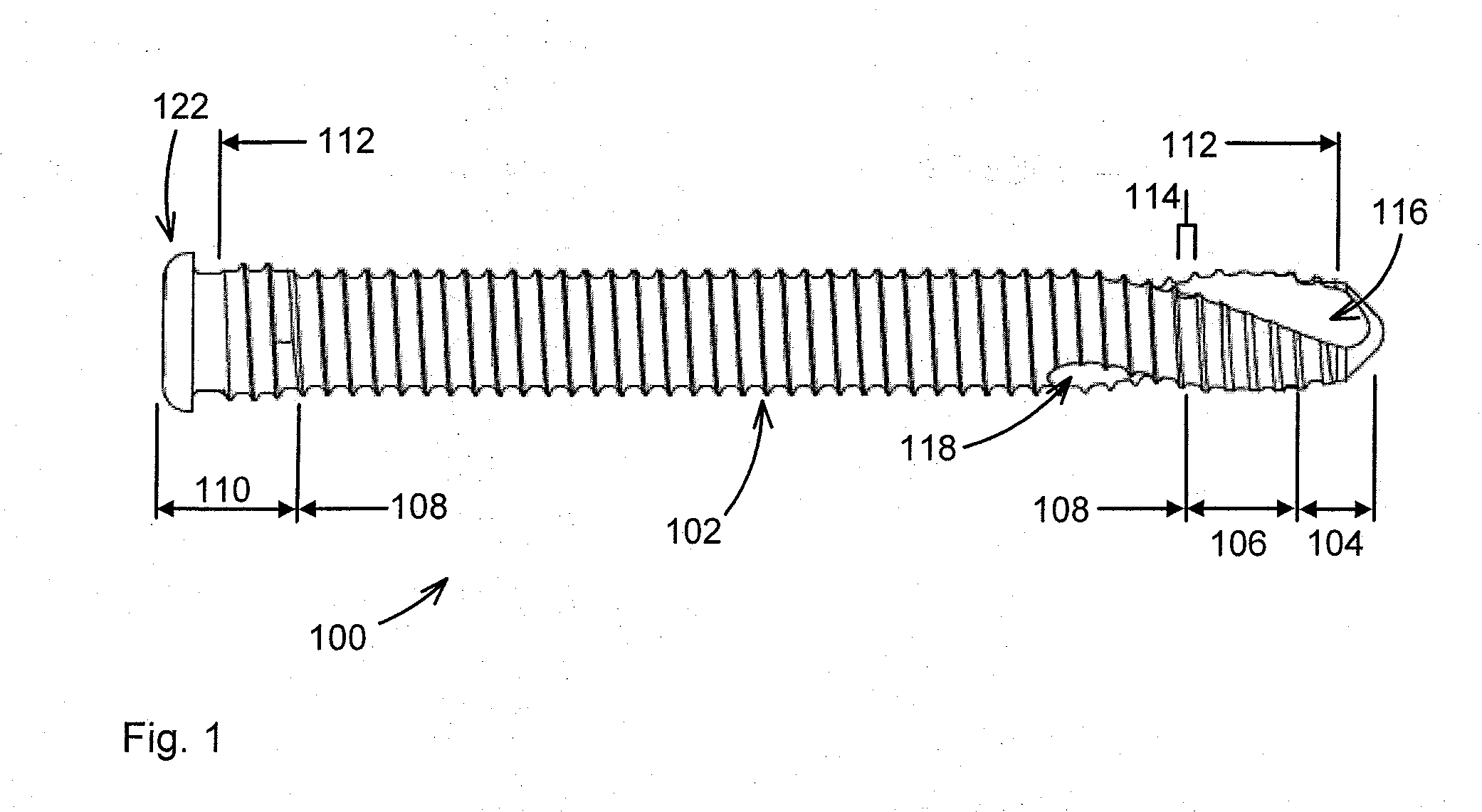
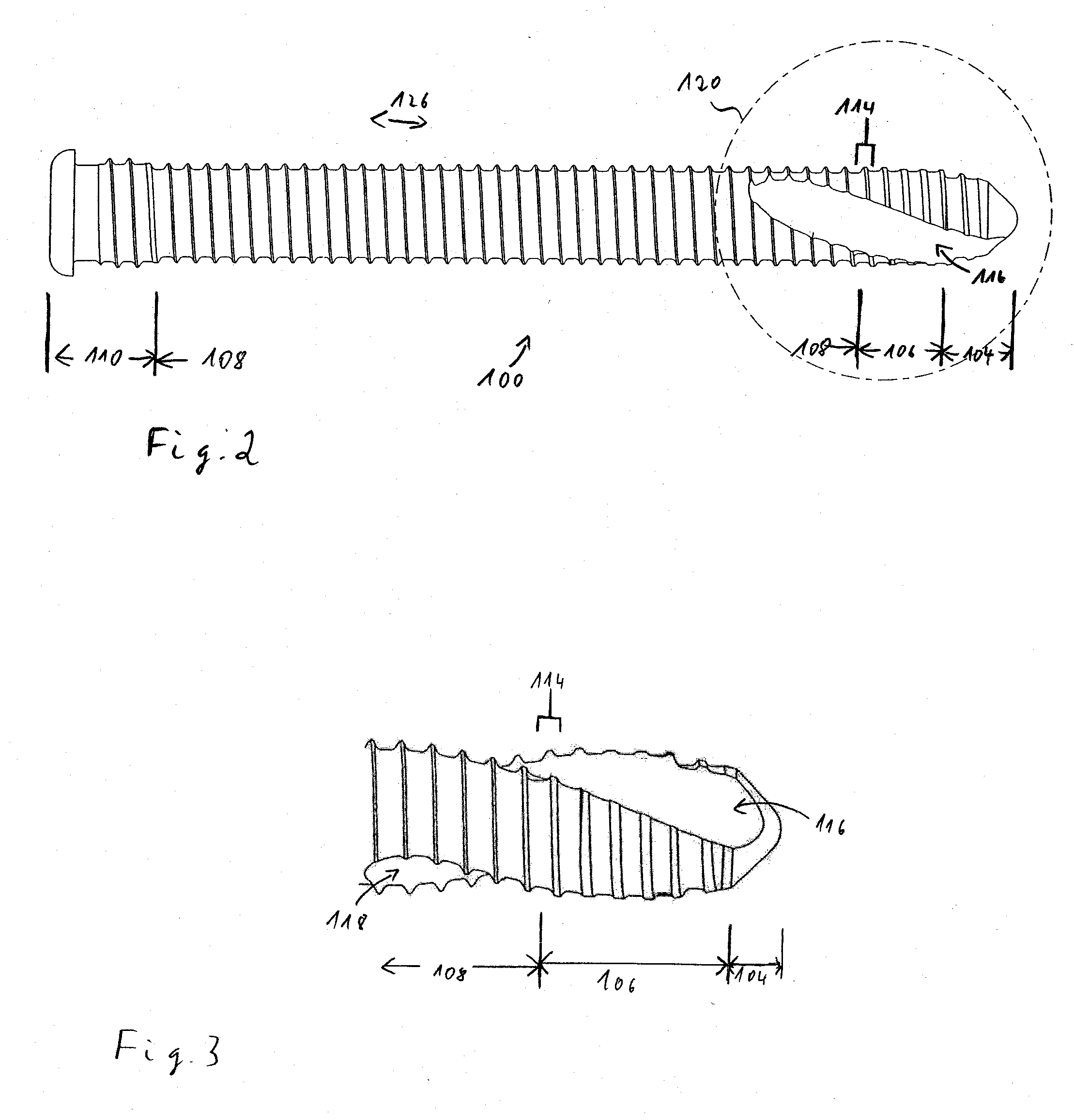
[0035]Firstly, with reference to FIGS. 1-7, a bone screw 100 which can be provided for example as a locking screw for use in osteosynthesis in the face / skull region is explained. FIG. 1 shows a side view of the bone screw 100, which is designed as a self-tapping screw. The bone screw 100 has a screw shank 102 with a front tip 104, a cutting region 106, an intermediate region 108 and a head region 110. A thread extends over a threaded portion 112 which extends, in this embodiment, continuously from the tip 104 right up into the head region 110. In the front region of the screw shank 102, two helically wound grooves 116 and 118 for removing cut material are provided.

[0036]FIG. 2 shows the bone screw 100 in a view rotated by a quarter turn about the longitudinal axis. A detail of the side views of the screw 100 from FIGS. 1 and 2 (see in FIG. 2 the detail denoted by the circle 120) is illustrated in enlarged manner in FIGS. 3 and 4, respectively. It can be seen, for example, from FIG...

embodiment 500

[0061]FIG. 9 shows a further embodiment 500 of a bone screw, in which the head region 502 is designed differently again than in the screws 100 and 400. The head region 502 is designed in particular thread-free. The diameter of the head region 502 corresponds to the root diameter of the intermediate region 504.

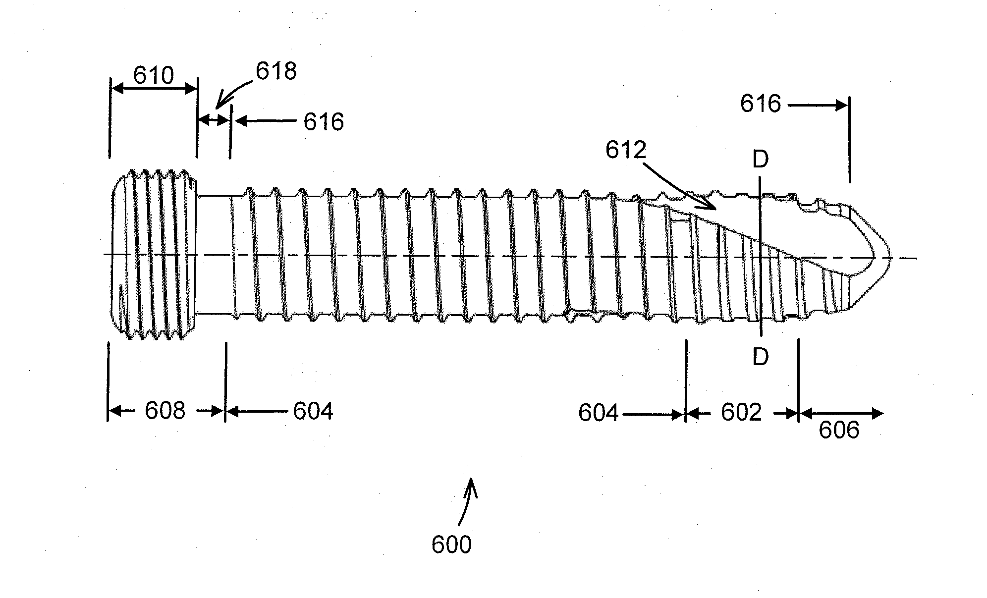
[0062]FIG. 10 shows a further embodiment of a bone screw 600. As the preceding embodiments, the screw 600 also has in the cutting region 602 an enlarged root diameter in comparison with the intermediate region 604. The outside diameter of the screw is constant in the cutting region and in the intermediate region. The obtuse screw tip 606 has an opening angle of 90°. A head region 608 has an enlarged head part 610 with its own thread.

[0063]FIG. 11 shows the screw 600 from the front and FIG. 12 shows a section through the screw 600 along the line D-D in the cutting region 602. There can be seen two tapering grooves 612, 614 which can be configured in the same way as for the groov...


PUM

PropertyMeasurementUnit
Diameteraaaaaaaaaa
Shapeaaaaaaaaaa

Abstract

The invention relates to a self-tapping bone screw, in particular for use as a compression screw or a locking screw for an implant. The bone screw has screw shank, which has a front tip, a cutting region, an intermediate region and a rear head region. In a transition region comprising mutually adjoining parts of the cutting region and the intermediate region the root diameter of the screw shank in the cutting region is greater than the root diameter of the screw shank in the intermediate region, and the outside diameter of the screw shank is constant.

Description

CROSS REFERENCE TO RELATED APPLICATIONS[0001]The present application claims the benefit of European Patent Application No. 09 002 104.9, filed in the European Patent Office on Feb. 16, 2009, entitled “Bone screw and method of manufacturing same”, the disclosure of which is hereby incorporated herein by reference.BACKGROUND OF THE INVENTION[0002]The disclosure relates to a self-tapping bone screw, in particular for use as a compression screw or a locking screw for an implant. The disclosure further relates to a manufacturing method for such a bone screw.[0003]Bone screws are screws which are screwed into bones. Basically, bone screws are used in two different ways: In a first application bone screws serve to fix bones or bone fragments in a desired position relative to one another. In this case, the bone screw is used alone. In a second application the bone screw is used as a compression screw or a locking screw in order to position additional elements as fixation elements in or on t...

Claims


Application Information

Patent Timeline
IPC IPC(8): A61B17/86B21H3/02
CPCA61B17/8635A61B17/863
Inventor CHRISTEN, ALEXISMARKOVIC, ZELJKO
Owner STRYKER EURO OPERATIONS HLDG LLC
Why Eureka
Try Eureka