Flexible conduit with pressure vault interlocked from below

a technology of pressure vault and flexible conduit, which is applied in the direction of flexible pipes, mechanical devices, pipes, etc., can solve the problems of reducing the life of profile wires, limiting the performance of pressure vaults in dynamic applications, and weak fasteners that cannot withstand dynamic stressing, so as to achieve constant outside diameter and better stress distribution

Inactive Publication Date: 2005-05-10
TECH FRANCE SA
View PDF18 Cites 37 Cited by
  • Summary
  • Abstract
  • Description
  • Claims
  • Application Information

AI Technical Summary

Benefits of technology

[0025]The present invention achieves its objective by means of a flexible tubular pipe of the rough-bore or smooth-bore type, that is to say comprising at least, from the inside outwards, an internal sealing sheath made of a polymer material, a cylindrical pressure vault having an external face and an internal face placed over the internal sheath, the vault consisting of the winding, in a helix with a short pitch and with a gap between turns, of a metal profile wire interlocked from below by a fastener wire, at least one ply of tensile armour layers wound with a long pitch and an external protective sealing sheath made of a polymer, characterized in that the fastener wire has substantially the same height as the profile wire and is interlocked, with no nominal radial contact, below the neutral fibre of the wire (that is to say the fibre where there is no elongation during spiralling, at the centre of mass of the cross section of the wire). The expression “with no nominal radial contact” is understood to mean that the profile wire and the fastener wire are shaped with a nominal radial clearance at their interlocking regions. In practice, the interlocking region, defined by the mean plane of the interlocking, is located at the level of the lower ⅓ of the height of the profile wire and of the fastener wire, or lower. This interlocking from below makes it possible to avoid the problem of the internal sheath creeping. The height and the cross section of the fastener wire contributes to the lack of radial contact between the fastener wire and the profile wire; consequently, the fastener wire absorbs and transmits the pressure stresses to the outside of the vault. The fastener wire is dimensioned so as to allow it to withstand the stresses due to the internal pressure without the contribution of the profile wire; thus, there is no substantial transmission of stresses to the interlocking projections. It is advantageous for the cross section of the fastener wire to be similar to the cross section of the profile wire. In practice, the ratio of the cross section of the profile wire to the cross section of the fastener wire is between 1 and 2 (and preferably between 1 and 1.6), whereas in the prior art this ratio is greater than 2 and very often greater than 4 or 5. Likewise, the ratio of the moment of inertial Iyy of the profile wire to the moment of inertia Iyy of the fastener wire is advantageously between 1 and 2, thereby allowing the mean moment of inertia of the pressure vault not to be too greatly reduced compared with that of the profile wire alone. Advantageously, the height of the fastener wire is the same or approximately the same as the height of the profile wire. This makes it possible to have a constant outside diameter and a better distribution of the stresses.

Problems solved by technology

These contacts cause rubbing which, combined with the large bearing pressures, result in a reduction in the lifetime of the profile wires by fatigue cracking.
This problem is encountered, for example in the pipe known from U.S. Pat. No. 4,549,581 which shows the interlocking by U-shaped fasteners of the U-shaped wires from below.
These fasteners are too weak to withstand the dynamic stressing.
This type of interlocking considerably limits the performance of the pressure vault in dynamic applications.
The internal sheath may creep into this large volume due to the effect of temperature and of the internal pressure, which results either in damage to the sheath or in disruption to the interlocking of the pressure vault.
This problem may be alleviated by providing the pressure sheath with additional thickness, but that increases the cost of this sheath.
However, the use of these devices increases the cost of manufacturing these pressure vaults.

Method used


Image

  • Flexible conduit with pressure vault interlocked from below
  • Flexible conduit with pressure vault interlocked from below
  • Flexible conduit with pressure vault interlocked from below

Examples


Embodiment Construction

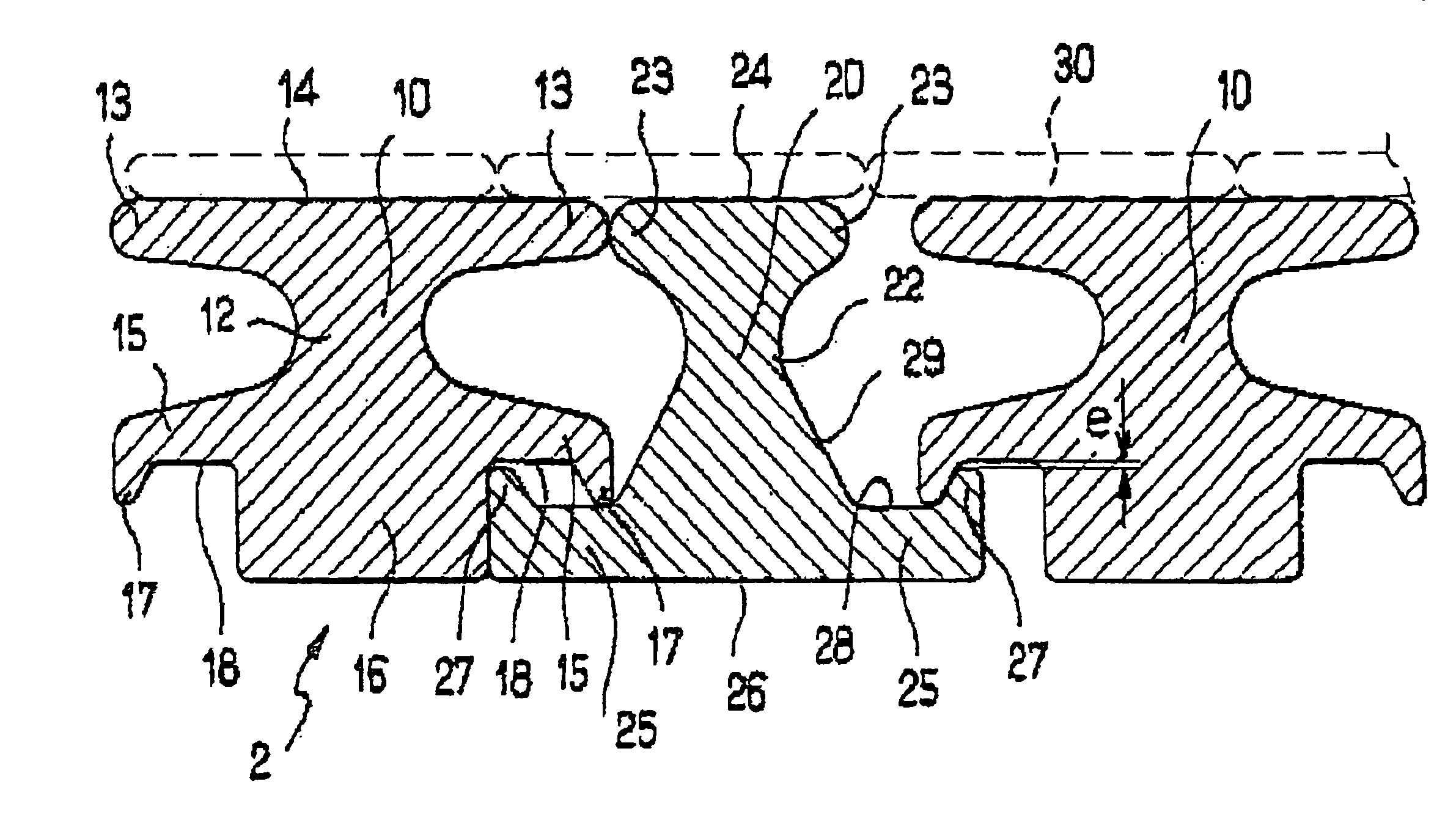
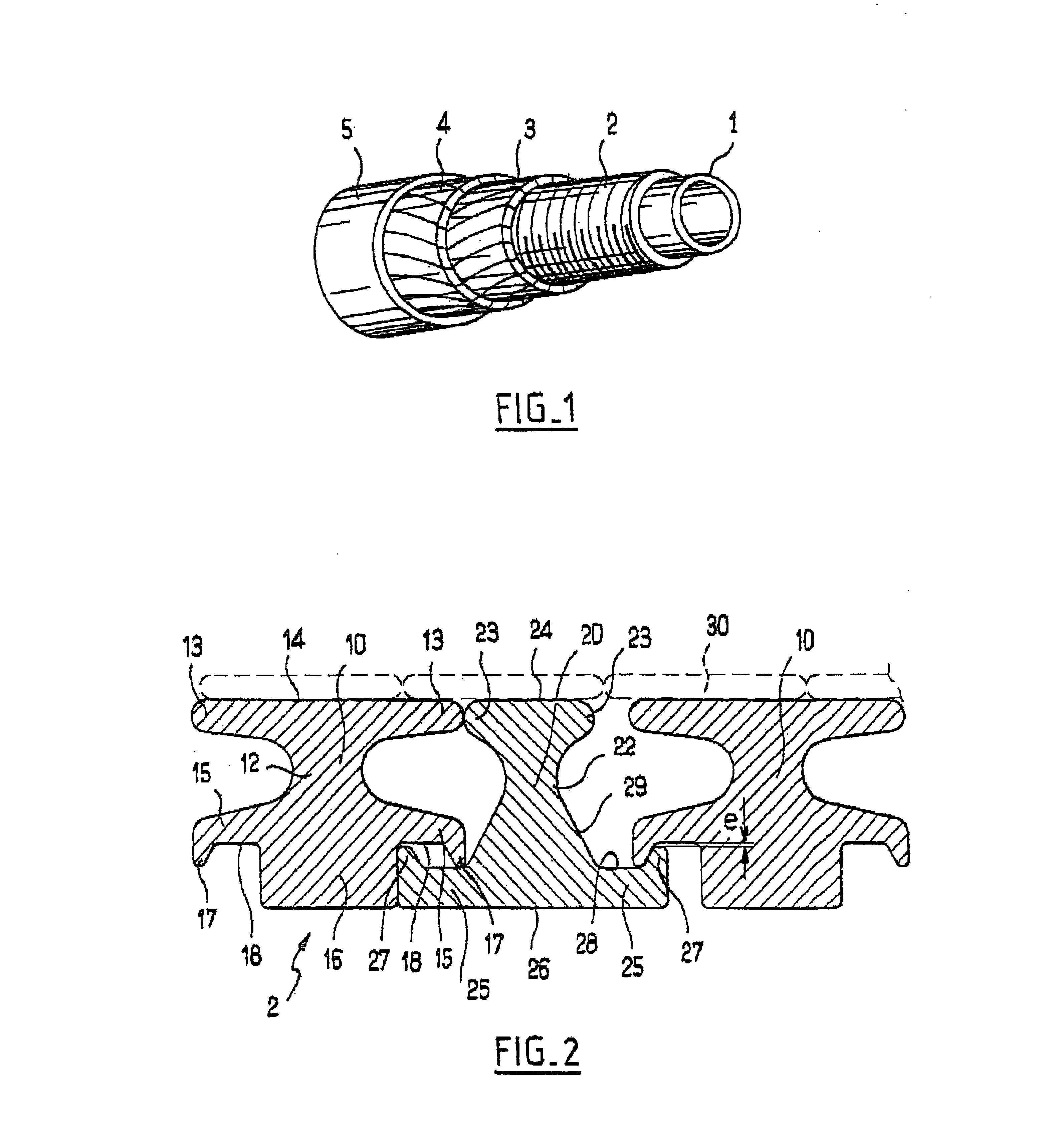
[0033]As FIG. 1 shows, and in general, a pipe of the smooth-bore type comprises, from the inside outwards, a polymeric internal sealing sheath 1, a metal vault 2 consisting of the winding of at least one interlocked metal profile wire in a helix, an armour layer resistant to the axial tension in the longitudinal direction of the pipe and usually consisting of one or more pairs of crossed plies 3, 4 wound in opposite directions, and a polymeric external sealing sheath 5. Other layers (not shown) may be provided, depending on the type and the application of the pipe, such as, for example, an internal carcass underneath the internal sealing sheath 1 (for rough-bore pipes), a hoop reinforcement layer consisting of a winding with a short pitch of a rectangular wire, interposed between the pressure vault 2 and the first armour ply 3, and intermediate sheaths placed between various armour plies.

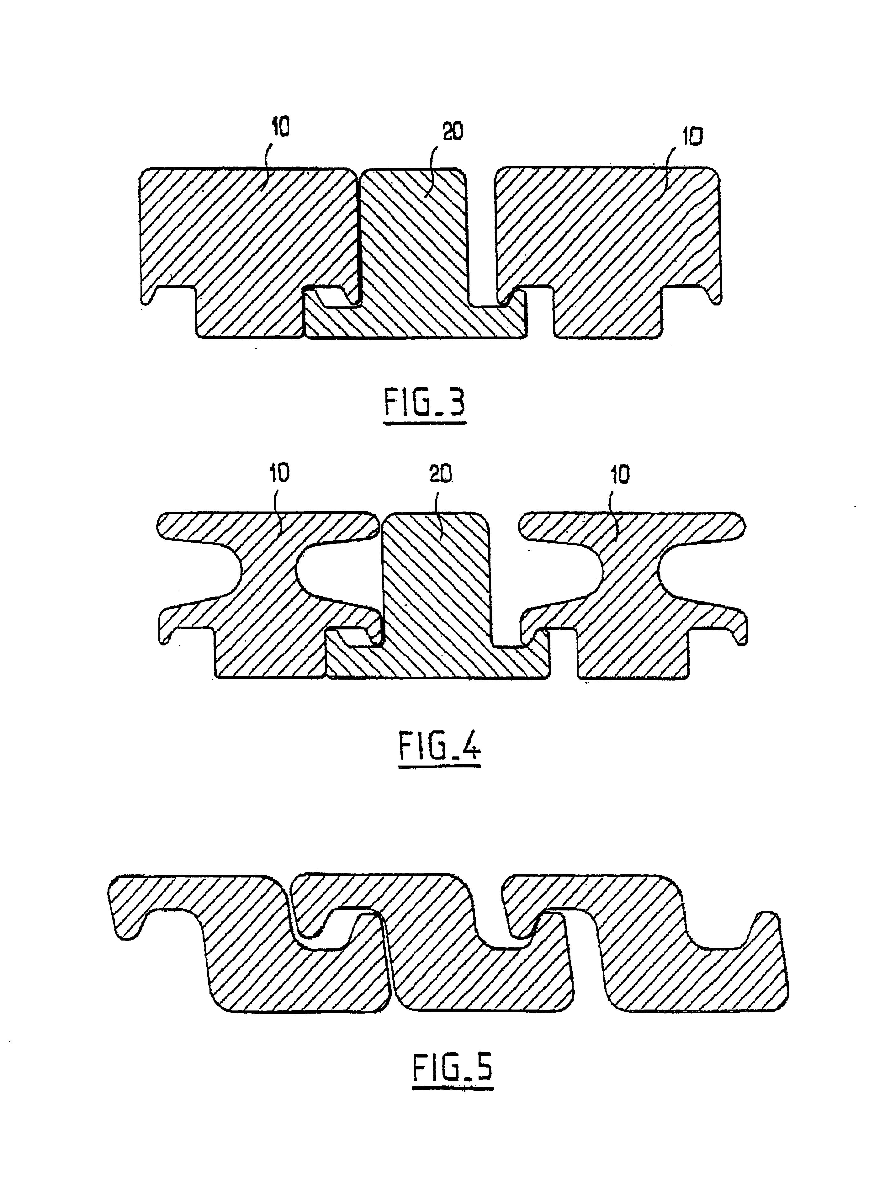
[0034]FIGS. 5 to 8 show known pressure vaults from the prior art. FIG. 5 shows an unsymmetrical ...


PUM


Abstract

A flexible tubular pipe comprising at least, from the inside outwards, an internal sealing sheath made of a polymer material, a cylindrical pressure vault having an external face and having an internal face placed over the internal sheath. The vault is a winding, in a helix with a short pitch and with a gap between turns, of an interlocked metal profile wire. At least one ply of tensile armour layers is wound with a long pitch. An external protective sealing sheath is made of a polymer. The fastener wire has the same height as the profile wire and is fastened below the neutral fiber of the profile wire. The ratio of the cross section of the profile wire to the cross section of the fastening wire is between 1 and 2 and the ratio of the moment of inertia Iyy of the profile wire to the moment of inertia Iyy of the fastening wire is between 1 and 2.

Description

BACKGROUND OF THE INVENTION[0001]The present invention relates to a flexible pipe for transporting, over long distances, a fluid which is under pressure and possibly at a high temperature, such as a gas, petroleum, water or other fluids. The invention relates most particularly to a pipe intended for offshore oil exploration. It is known that there are, on the one hand, bottom pipes, called flow lines, that is to say flexible pipes which are unwound from a barge in order to be laid generally on the bottom of the sea and connected to the subsea installations, such pipes working mainly in static mode, and, on the other hand, rising columns, called risers, that is to say flexible pipes which are unwound from a surface installation such as a platform and are connected to the subsea installations and most of which do not lie on or below the seabed, such pipes working essentially in dynamic mode. The invention relates more particularly to pipes working in dynamic mode.[0002]The flexible pi...

Claims


Application Information

Patent Timeline
Patent Type & Authority Patents(United States)
IPC IPC(8): F16L11/08
CPCF16L11/16F16L11/083
Inventor COUTAREL, ALAINDUPOIRON, FRAN.CEDILLA.OISESPINASSE, PHILIPPEJUNG, LOUIS PATRICE JOEL
Owner TECH FRANCE SA
Why Eureka
Try Eureka