Automatic lateral tilt control of a header in stubble height mode using machine level sensor

a technology of lateral tilt control and machine level sensor, which is applied in the direction of picking devices, agricultural tools and machines, picking devices, etc., can solve the problems of tire deformation, ground compaction, and inability to meet the needs of use, and achieve the effect of less difference and greater differen

Active Publication Date: 2010-08-26
BLUE LEAF I P INC
View PDF28 Cites 10 Cited by
  • Summary
  • Abstract
  • Description
  • Claims
  • Application Information

AI Technical Summary

Benefits of technology

[0012]According to yet another preferred embodiment of the invention, the predetermined amount of difference allowed between the lateral tilt angle of the machine and the angle of the laterally inclined surface is based on a vertical height of the header above the surface. The predetermined amount is larger, allowing a greater difference between the angles, when the header is positioned at a larger vertical cutting height. Conversely the predetermined amount is smaller, allowing less difference between the angles, when the header is positioned at a lower vertical cutting height.

Problems solved by technology

Thus typical ground sensing capability, if present at all, is unavailable or inoperable when the machine is operating in the stubble mode.
When the machine is disposed on a laterally inclined surface, downward and sideward forces acting on it can result in tire deformation, ground compaction, and the like on the downhill side.
However, for longer headers this angular difference causes a more pronounced height difference at the ends of the header such that the downhill side of the header may ride significantly closer to the surface than the uphill side.
In some circumstances, this may lead to undesirably uneven cutting height and risks possible damage to the cutting apparatus due to impact with the ground.

Method used


Image

  • Automatic lateral tilt control of a header in stubble height mode using machine level sensor
  • Automatic lateral tilt control of a header in stubble height mode using machine level sensor
  • Automatic lateral tilt control of a header in stubble height mode using machine level sensor

Examples


Embodiment Construction

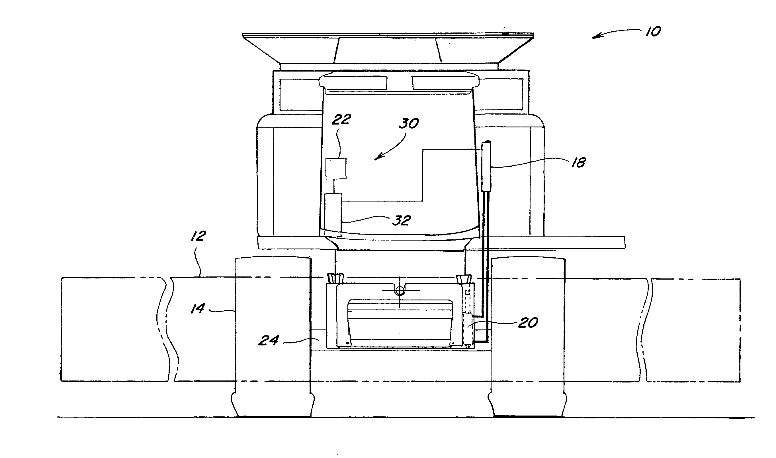
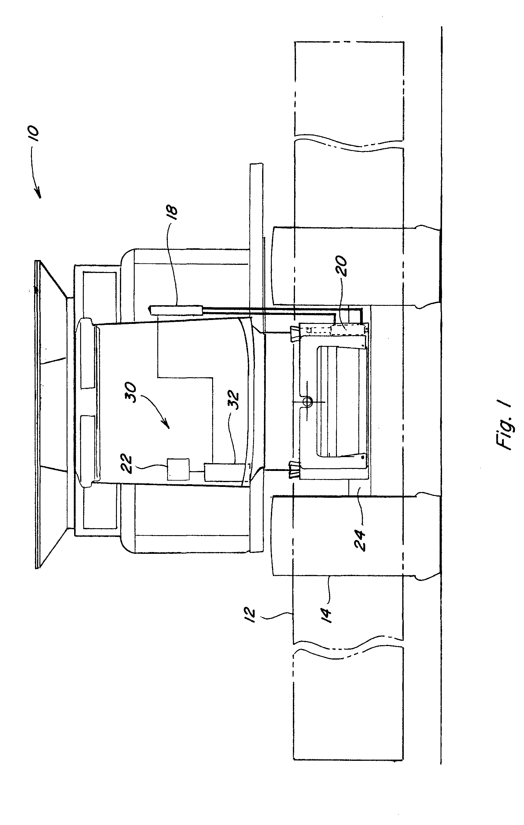
[0022]Referring now to the drawings, FIG. 1 depicts a simplified front view of a representative self propelled agricultural plant cutting machine, such as a combine 10, including a plant cutting header 12 mounted thereon. Combine 10 is intended to be representative of a wide variety of agricultural plant cutting and harvesting machines and other work machines having header 12 which is desired or required to be positioned at one or more selectable cutting heights in relation to the surface, and angles of sideward tilt in relation to the machine itself, as well as to a surface over which the machine is driven. When header 12 is positioned at a cutting height above the surface, such that the stalks of crops are left at a higher level, combine 10 is sometimes referred to as operating in a “stubble mode”. Since conventional ground sensing capability is generally only useful when header 12 is positioned very close to, or on, the surface, typical ground sensing capability, if present at al...


PUM


Abstract

A system and method for controlling the lateral tilt of a header of an agricultural plant cutting machine, such as, but not limited to, a combine, windrower or the like, and more particularly, to an automatic lateral tilt control system for precisely controlling an angle of lateral tilt of the header relative to the machine based on a lateral tilt angle of the machine relative to a reference and at least one additional characteristic such that, when the machine is disposed on a laterally inclined surface, and the machine is at a tilt angle differing from an angle of the laterally inclined surface, the angle of lateral tilt of the header relative to the machine is responsively adjusted so an angle of the lateral tilt of the header relative to the reference is substantially equal to the angle of the laterally inclined surface, the system especially useful when operating in a stubble mode and traversing inclined surfaces.

Description

TECHNICAL FIELD [0001]This invention relates generally to a system and method for controlling the angle of lateral tilt of a header of an agricultural plant cutting machine, such as, but not limited to, a combine, windrower or the like, when disposed on a laterally inclined surface and more particularly, to an automatic lateral tilt control system which precisely controls an angle of lateral tilt of the header relative to the machine based on a lateral tilt angle of the machine relative to a reference and at least one additional characteristic.BACKGROUND ART [0002]Agricultural plant cutting and harvesting machines typically have a header which is desired or required to be positioned at one or more selectable cutting heights in relation to the surface, and angles of sideward tilt in relation to the machine itself, as well as to a surface over which the machine is driven. When the header is positioned at a cutting height above the surface, such that the stalks of crops are left at a h...

Claims


Application Information

Patent Timeline
Patent Type & Authority Applications(United States)
IPC IPC(8): A01D75/28
CPCA01D75/287
Inventor DIGMAN, MICHAEL J.
Owner BLUE LEAF I P INC
Why Eureka
Try Eureka