Display device and method of controlling same

Active Publication Date: 2017-02-02
CANON KK
View PDF6 Cites 6 Cited by
  • Summary
  • Abstract
  • Description
  • Claims
  • Application Information

AI Technical Summary

Benefits of technology

[0007]With the dual-layer LCD technology, as described above, there are cases where a phenomenon of a double image occurs depending on the angle of observation. However, there are images less likely to decrease in visibility (less likely to appear as a double image), even with a dual-layer LCD. For example, with images such as a natural image or a diagnostic mammogram in which changes in tone are smooth, the phenomenon of a double image is less likely to occur even when displaying is made the same in

Problems solved by technology

This poses a problem of low visibility due to the

Method used


Image

  • Display device and method of controlling same
  • Display device and method of controlling same
  • Display device and method of controlling same

Examples


embodiment 1

[0030]A display device of Embodiment 1 of the present invention will be described.

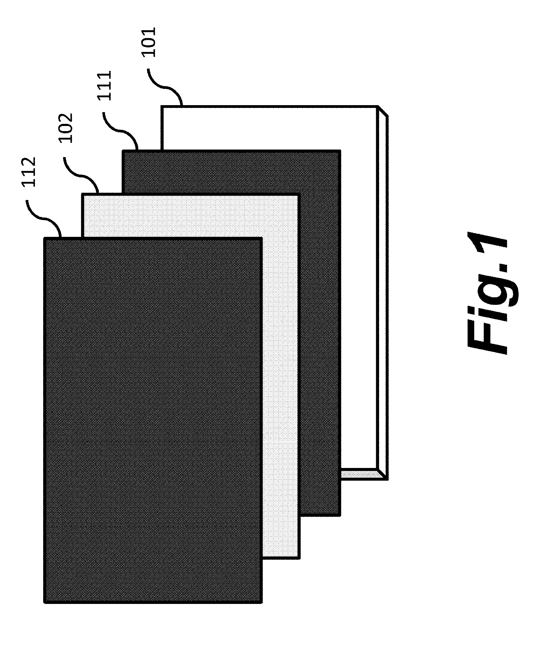
[0031]FIG. 1 is a block diagram showing the configuration of the display device in Embodiment 1.

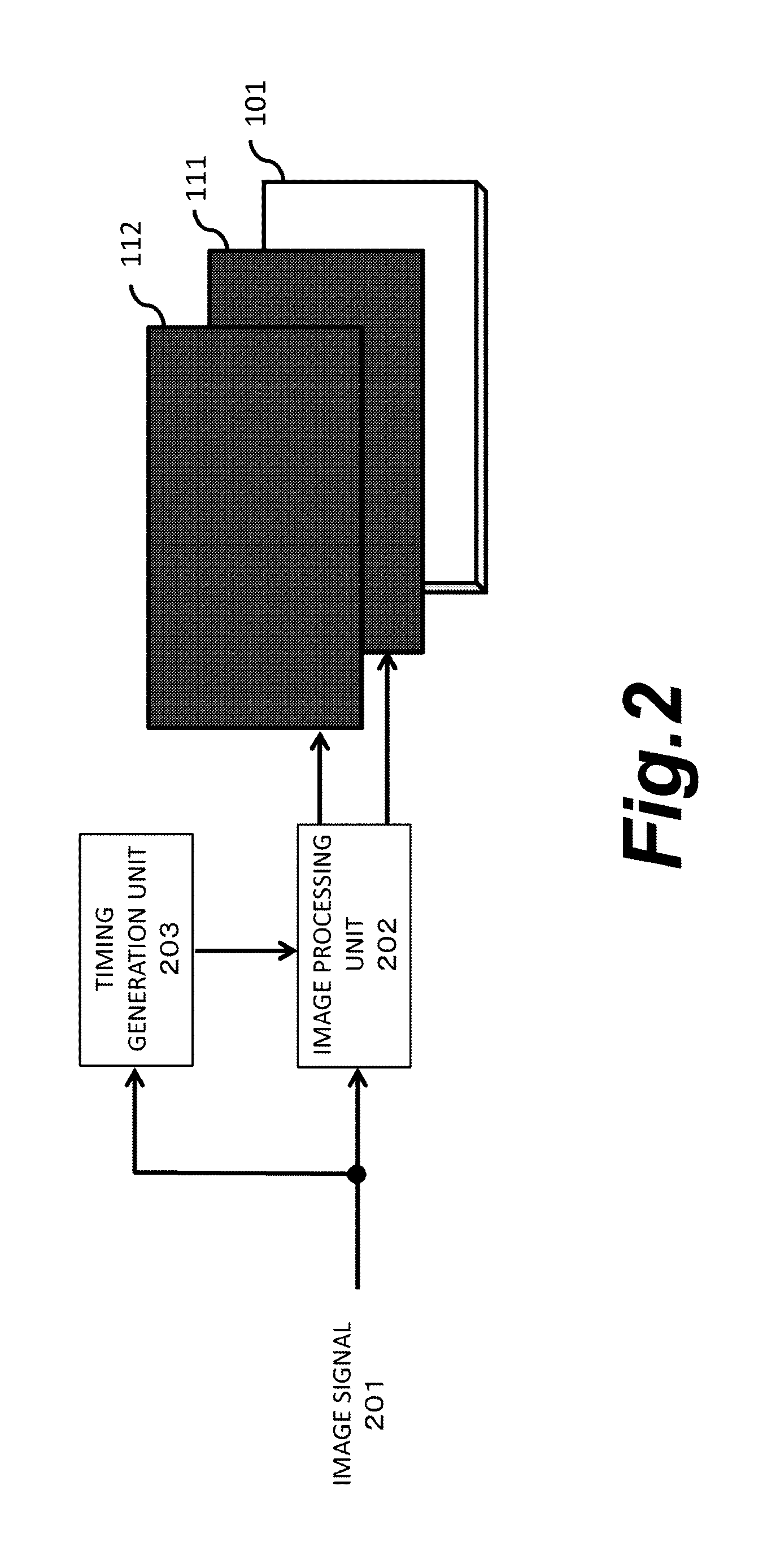
[0032]The display device includes, as a first display unit, a first liquid crystal panel 112 on the front side and, as a second display unit, a backlight 101 and a second liquid crystal panel 111 arranged on the backlight side to modulate light from the backlight 101. The second liquid crystal panel 111 is visible through the first liquid crystal panel 112. In order to prevent moiré, in the case of providing two layers of the liquid crystal panels, the second liquid crystal panel 111 is provided on the back side of, and with a certain interval from, the first liquid crystal panel 112, or the second liquid crystal panel 111 is provided on the back side of the first liquid crystal panel 112 with an optical sheet such as a diffusion sheet 102 therebetween. In Embodiment 1, the configuration is such that the dif...

embodiment 2

[0060]A display device of Embodiment 2 will be described.

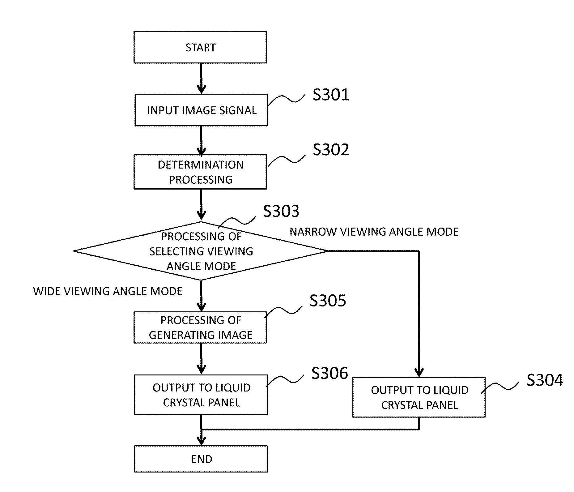
[0061]In Embodiment 2, it is assumed that first image data includes additional information showing the content of an image (whether the wide viewing angle mode is to be applied to the image or the narrow viewing angle mode is to be applied to the image). In this case, determination on the type of the image through an image analysis as in Embodiment 1 does not need to be performed. In Embodiment 2, as shown in FIG. 10, the image processing unit 202 performs processing of acquiring additional information showing the content (type) of an image from the first image data in step S401, instead of step S302 in FIG. 3. In the subsequent step S303, the image processing unit 202 performs processing of selecting the wide viewing angle mode or the narrow viewing angle mode as the display mode, based on the additional information acquired from the first image data. With a configuration that allows various additional information to be trans...

embodiment 3

[0062]A display device of Embodiment 3 will be described.

[0063]Embodiment 3 assumes a case where the content (type) of an image is determined in advance for each area in the image. In this case, as shown in FIG. 11, the image processing unit 202 acquires information on the content of an associated image for each area in the image, in step S501 following step S301. In the subsequent step S502, the image processing unit 202 selects the narrow viewing angle mode or the wide viewing angle mode in accordance with the content of the image for each area. The display mode may be determined in advance for each area in the image. In this case, the image processing unit 202 acquires information on the associated display mode for each area in the image to perform selecting the narrow viewing angle mode or the wide viewing angle mode based on the acquired display mode.

[0064]A viewer for a medical image as shown in FIG. 12 is an example in which the type of a display image is determined for each ...


PUM


Abstract

Provided is a display device including a first display unit, a second display unit arranged on a back side of the first display unit, a generation unit configured to perform predetermined image processing on first image data to generate second image data, and a control unit configured to select one of a plurality of display modes including a first display mode on which the first display unit displays an image based on the first image data and the second display unit displays an image based on the second image data, and a second display mode on which the first display unit and the second display unit display the image based on the first image data.

Description

BACKGROUND OF THE INVENTION[0001]Field of the Invention[0002]The present invention relates to a display device and a method of controlling the same.[0003]Description of the Related Art[0004]One scheme for achieving high-contrast display in liquid crystal display devices is the dual-layer LCD technology. The dual-layer LCD technology considerably improves the contrast by superimposing two liquid crystal panels, relative to a structure using one liquid crystal panel.[0005]In the dual-layer LCD technology, space is often provided between the liquid crystal panels upon arranging liquid crystals into two layers, in order to prevent scratches or the like caused by contact of the liquid crystal panels. Even without the space being provided between the liquid crystal panels, space due to the thickness of the liquid crystal panel itself exists. With the influence of the space, there are cases where images displayed in same positions on the two liquid crystal panels appear to be in differing ...

Claims


Application Information

Patent Timeline
IPC IPC(8): G06T11/60G06F3/14G09G3/36G06T7/00G09G3/3208
CPCG06T11/60G06T7/004G09G2320/0626G09G3/36G06F3/1423G09G3/3208G09G3/3611G09G2300/023G09G2320/028G09G2320/068G09G2358/00G09G2380/08
Inventor KAMIYOSHIHARA, MASAHIRO
Owner CANON KK
Why Eureka
Try Eureka