[0020]An object of the present invention is to provide a grazing incidence interferometer which, without adopting a special configuration, makes it possible to prevent the wave front error of the beam emitted from the beam source section from affecting the measurement accuracy, and is capable of rendering the ease of use excellent.
[0022]According to the present invention, since the orientation of the wave front of the measuring beam or the reference beam is inverted by the image inverting part which is provided in the optical path of the measuring beam or the reference beam leading from the
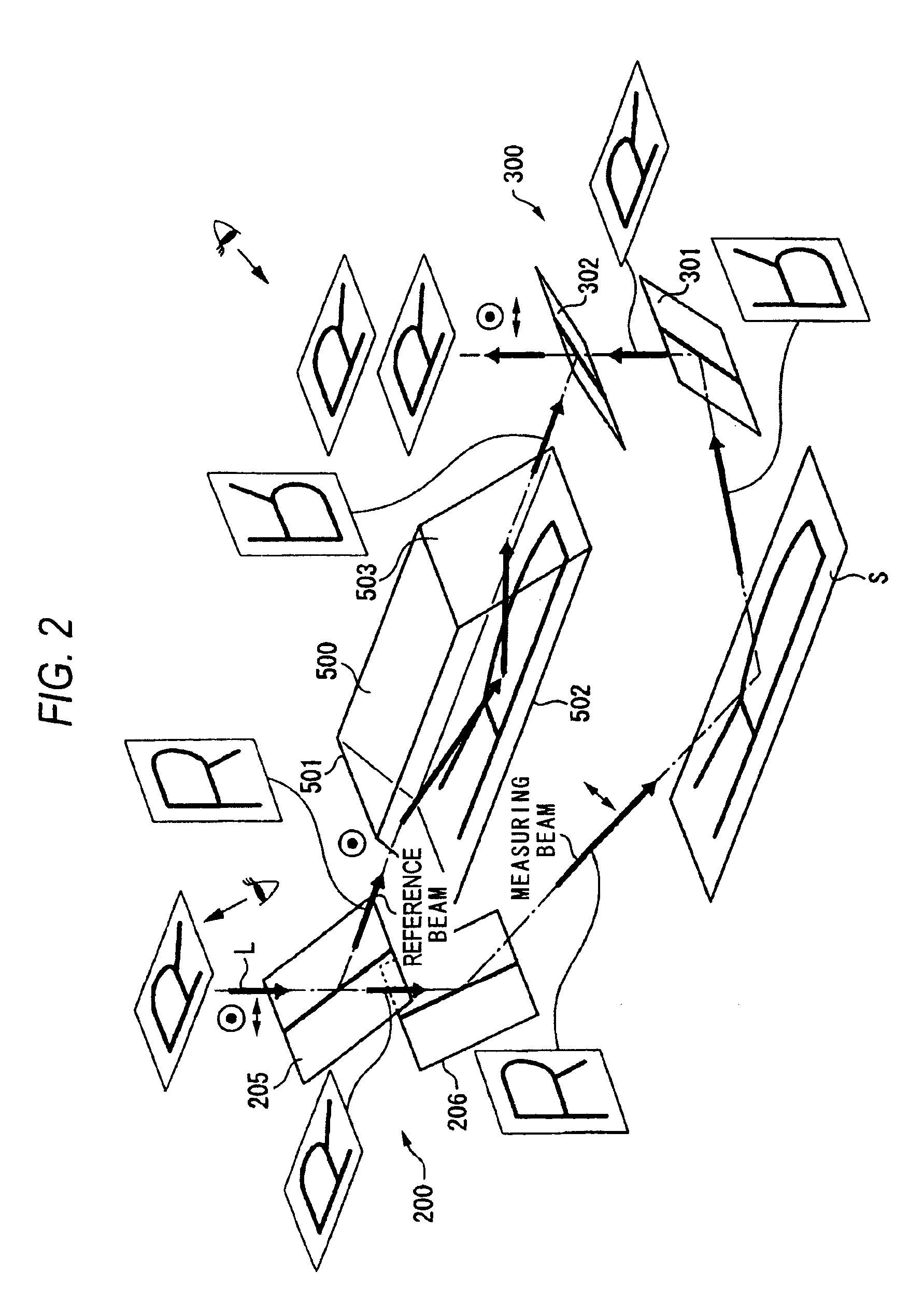
beam splitting section to the beam combining section, it is possible to properly arrange the orientations of the wave fronts of the measuring beam and the reference beam of the combined beam components are arranged properly. Therefore, in the interference fringe which is formed by the combined beam, it is possible to cancel the wave front error of the beam emitted from the beam source section, thus making it possible to prevent the wave front error from affecting the measurement accuracy. The reference beam and the measuring beam are emergent from the beam splitting section and, after respectively travelling along different optical paths, are combined by the beam combining section. Accordingly, since the grazing incidence interferometer in accordance with the present invention is configured as a non-
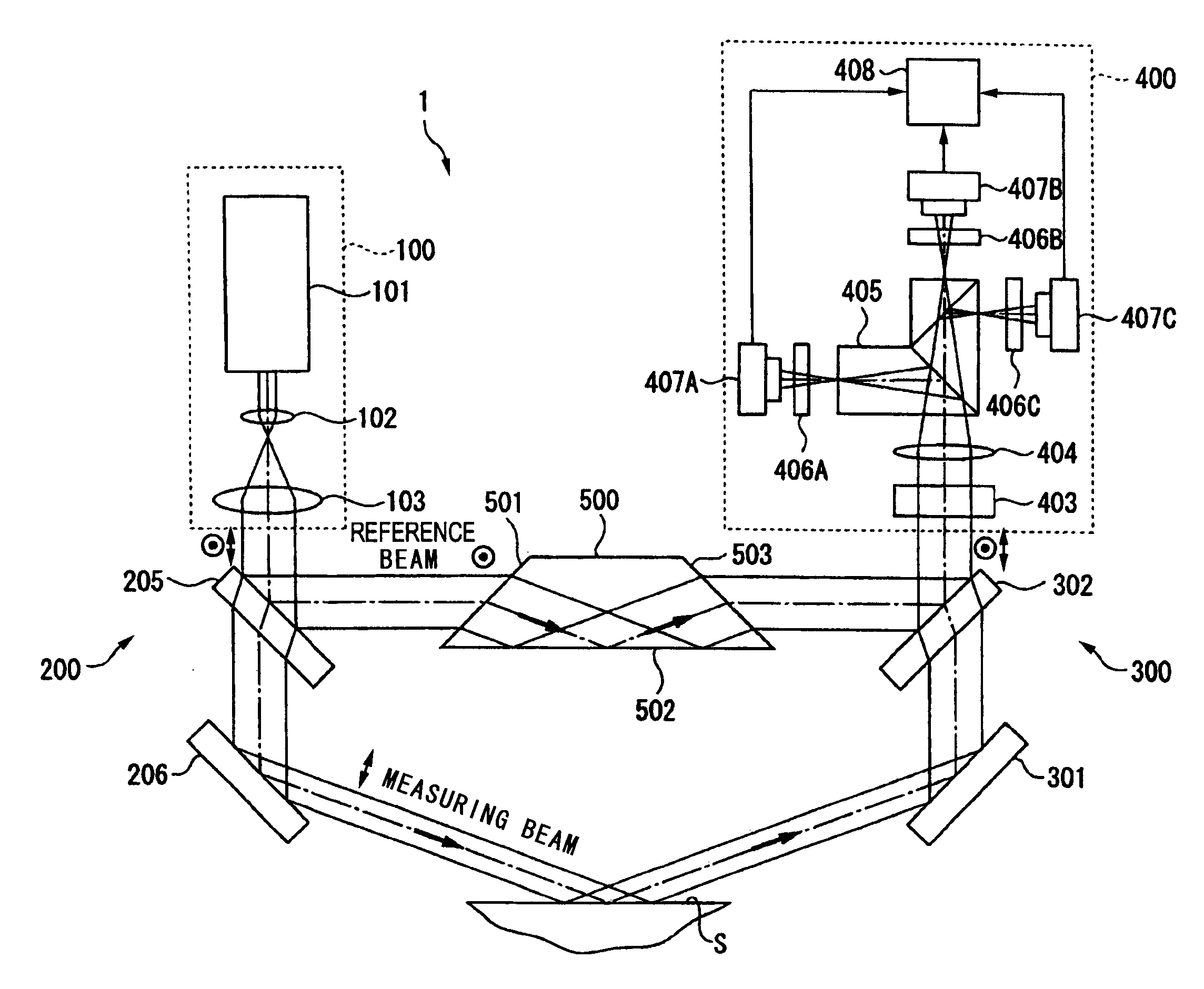
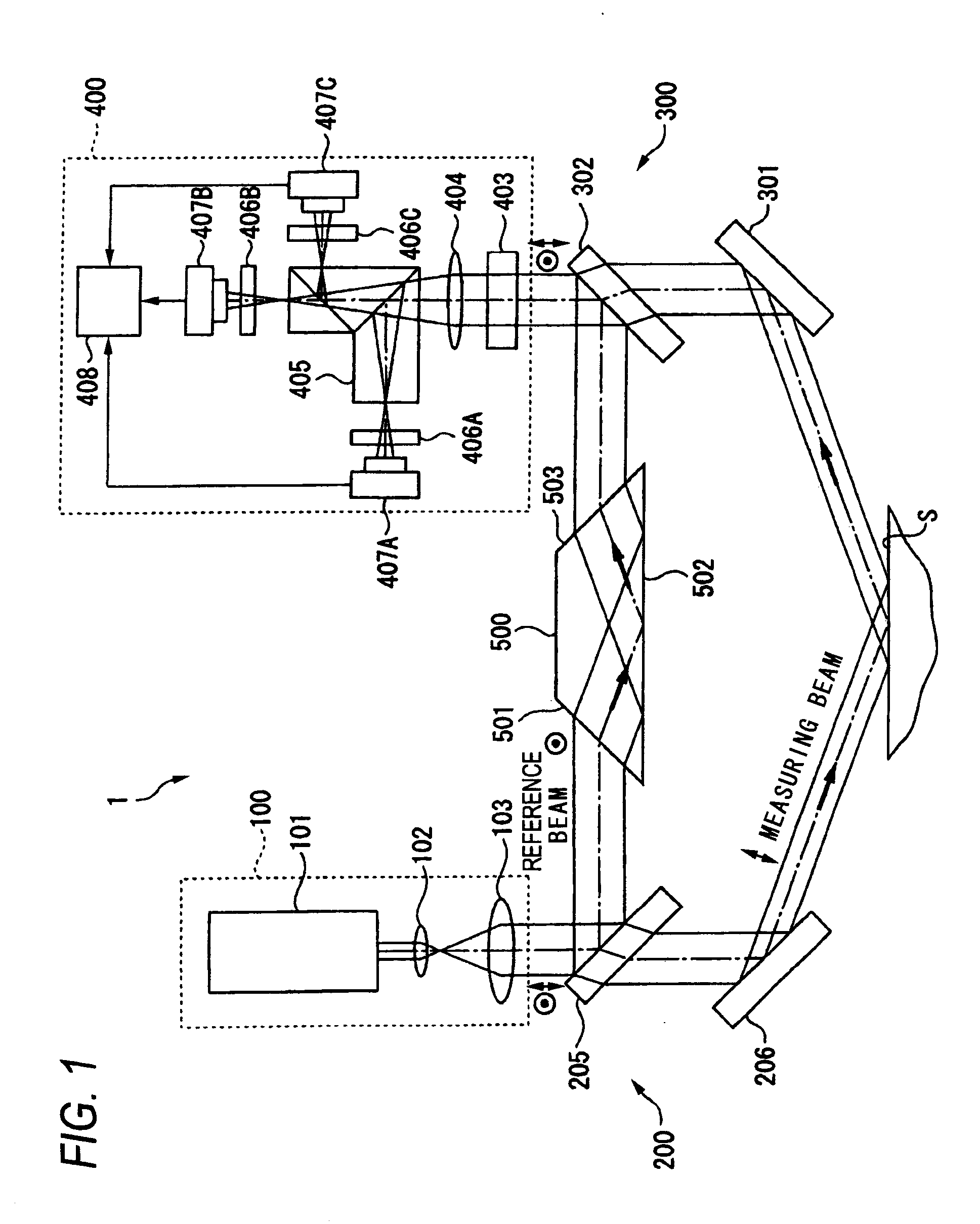
common path type, it is unnecessary to precisely conduct management of distance between, on the one hand, the beam splitting section and the beam combining section and, on the other hand, the measurement surface, so that the ease of use can be made excellent. The beam splitting section causes the reference beam to emerge in an attitude in which the reference beam directly reaches the combining section. Accordingly, since the basic configuration is similar to that of a general conventional non-common path type grazing incidence interferometer (e.g., the grazing incidence interferometer 1E in FIG. 7i, the grazing incidence interferometer in accordance with the present invention can be obtained by providing the image inverting part in the optical path of the measuring beam or the reference beam of the conventional grazing incidence interferometer, so that fabrication can be facilitated. As described above, in accordance with the present invention, it is possible to prevent the wave front error of the beam emitted from the beam source section from affecting the measurement accuracy and to render the ease of use excellent without adopting a special configuration.
[0023]The image inverting part may be provided in the optical path of the reference beam leading from the beam splitting section to the beam combining section. Here, the reference beam is made emergent from the beam splitting section with an attitude of directly reaching the beam combining section, while the measuring beam is made emergent obliquely from the beam splitting section toward the measurement surface, and after undergoing reflection at the measurement surface, reaches the beam combining section. Therefore, the optical path of the reference beam becomes shorter than the optical path of the measuring beam. If the difference in the
optical path length between the reference beam and the measuring beam becomes greater than the coherent distance of the beam emitted from the beam source section, there is a possibility that the contrast of the interference fringe declines and the measurement accuracy disadvantageously deteriorates. In the present invention, however, since the image inverting part is provided in the optical path of the reference beam, the
optical path length of the reference beam can be made large by the image inverting section, so that the difference in the
optical path length between the reference beam and the measuring beam can be set to less than the coherent distance. For this reason, the contrast of the interference fringe can be made excellent, thus allowing the measurement accuracy to be maintained satisfactorily.
[0025]According to the present invention, the image inverting part is constituted by a
dove prism for inverting the orientation of the wave front of the
incident beam by once reflecting the
incident beam at its bottom surface. As for the
dove prism, since its incident direction and its emergent direction are identical, the
dove prism can be easily provided in the optical path of the measuring beam or the reference beam of the conventional grazing incidence interferometer, so that the fabrication can be facilitated. Additionally, since the dove prism has a greater
refractive index than the air, the optical
path length of the
incident beam can be made large. For this reason, the optical
path length of the reference beam can be enlarged by the provision of the dove prism in the optical path of the reference beam, so that the difference in the optical
path length between the reference beam and the measuring beam can be set to less than the coherent distance.
[0026]The image inverting part may include a plurality of reflection mirrors, reflects an incident beam three times by the plurality of reflection mirrors, and after inverting its wave front, makes the beam emergent along a direction identical to an incident direction. According to the present invention, as the incident beam is reflected an odd number of times by the plurality of reflection mirrors, the image inverting part inverts the orientation of the wave front of the incident beam and makes it emergent to outside the image inverting part. As for this image inverting part as well, since its incident direction and its emergent direction are identical, the image inverting part can be easily provided in the optical path of the measuring beam or the reference beam of the conventional grazing incidence interferometer, so that the fabrication can be facilitated. Additionally, since the image inverting part reflects within it the incident beam an odd number of times, the optical path length of the incident beam can be made large. For this reason, the optical path length of the reference beam can be enlarged by the provision of the image inverting part of the invention in the optical path of the reference beam, so that the difference in the optical path length between the reference beam and the measuring beam can be set to less than the coherent distance.
[0028]According to the present invention, the beam splitting section and the beam combining section are respectively provided with bending members constituted by, for instance, reflection mirrors for bending the optical path of the measuring beam, apart from the splitting member and the combining member. Accordingly, by adjusting the attitudes of the respective bending members of the beam splitting section and the beam combining section, it is possible to easily change the
angle of incidence of the measuring beam with respect to the measurement surface.

