Screen-noise eliminating apparatus and cathode-ray tube display apparatus

a display apparatus and cathode ray tube technology, applied in the direction of color television details, television systems, picture reproducers using cathode ray tubes, etc., can solve the problems of considerable variation in image quality and horizontal-line noise degree, and achieve the effect of preventing the scanning line of a tv screen, extending the range of adequate viewing distance, and not degrading image quality

Inactive Publication Date: 2005-03-22
MITSUBISHI ELECTRIC CORP
View PDF23 Cites 8 Cited by
  • Summary
  • Abstract
  • Description
  • Claims
  • Application Information

AI Technical Summary

Benefits of technology

The present invention was invented to solve the above problems, and its primary object is to provide a screen noise eliminating apparatus and a cathode-ray tube display apparatus capable of preventing the scanning lines of a TV screen from being seen as the horizontal-line noise without degrading the image quality, and extending the range of the adequate viewing distance. Another object of the present invention is to obtain a screen noise eliminating apparatus and a cathode-ray tube display apparatus capable of providing a high image quality and less difference between the image qualities in the vertical and horizontal directions in any location across the entire display screen. Still another object of the present invention is to obtain a screen noise eliminating apparatus and a cathode-ray tube display apparatus capable of adequately switching the image quality according to the viewing distance.

Problems solved by technology

In a prior art cathode-ray tube display apparatus, the gaps between scanning lines are assumed to be unseen due to the low-pass characteristic of human eyes, so that there has been problems in that an optimal image quality is obtained only from an adequate viewing distance, and when a TV screen is viewed from a distance other than the adequate viewing distance, both the image quality and the degree of the horizontal-line noise are considerably varied depending on the viewing distance.

Method used


Image

  • Screen-noise eliminating apparatus and cathode-ray tube display apparatus
  • Screen-noise eliminating apparatus and cathode-ray tube display apparatus
  • Screen-noise eliminating apparatus and cathode-ray tube display apparatus

Examples


embodiment 1

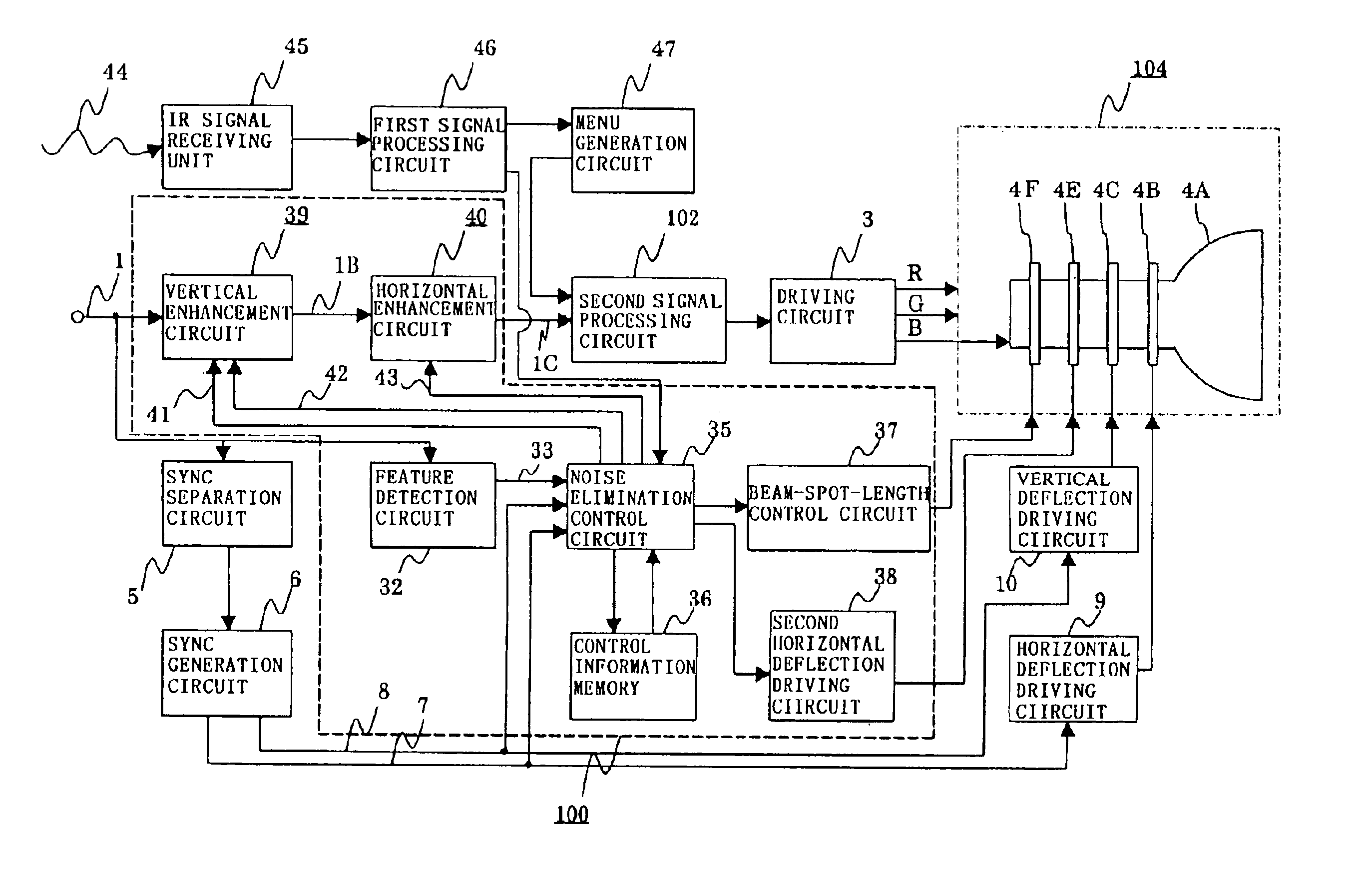
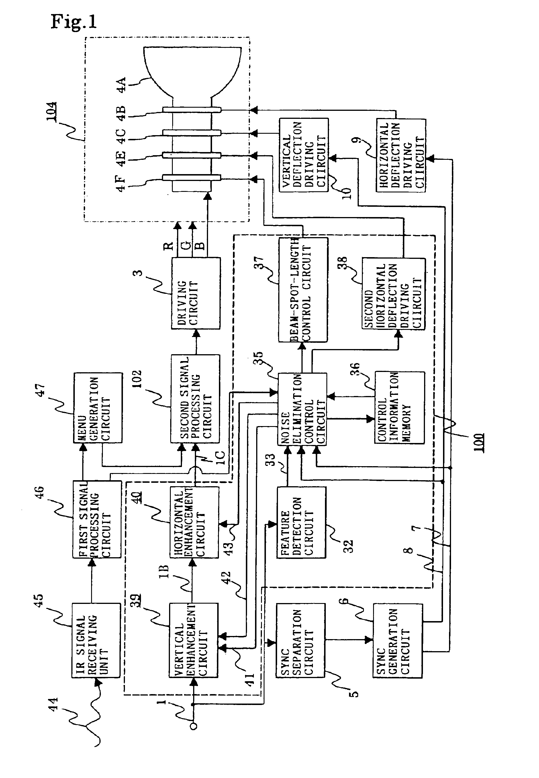
FIG. 1 is a schematic block diagram indicating a configuration according to the first embodiment of the present invention. Indicated in the diagram are, a TV signal 1, a driving circuit 3 for amplifying the signal level of each primary color signal and driving CRT cathodes, a CRT section 104 for green, blue, red colors, which comprises a CRT 4A for displaying the TV signal, a horizontal deflection coil 4B, a vertical deflection coil 4C, a second horizontal deflection coil 4E and a second vertical deflection coil 4F, a sync separation circuit 5 for separating a sync signal from the TV signal 1, a sync generation circuit 6, a horizontal sync signal 7 outputted from the sync generation circuit 6, a vertical sync signal 8 outputted from the sync generation circuit 6, a horizontal deflection driving circuit 9 for driving the horizontal deflection coil 4B according to the horizontal sync signal 7, and a vertical deflection driving circuit 10 for driving the vertical deflection coil 4C acc...

embodiment 2

In FIG. 1, the element 4F has been explained as being a second vertical deflection coil, however, it is not limited, and it may also be any other component, for example, an electromagnetic 4-pole focus coil or an electrical focus electrode such as electrostatic focus electrode or electromagnetic focus electrode. When the element 4F is constituted by any of the above alternatives, the beam-spot-length control circuit 37 shall, of course, be a circuit having a corresponding driving capability, such as an electrostatic focus driving circuit or an electromagnetic focus driving circuit. Also, the element 4F does not have to be provided separately when the TV system originally has any component having the same function, and any means capable of changing the vertical length of the beam spot at a changing speed that can follow the changes in an image signal may be shared for this function, and it may be configured by adding a modulation signal to an existing circuit.

Since these present embo...


PUM


Abstract

A screen-noise eliminating apparatus including beam-spot-length control means for increasing or decreasing the vertical length of a beam spot on a display screen generated by an electron of a cathode-ray tube for displaying a TV signal; vertical enhancement means for enhancing a given vertical-direction spatial frequency characteristic of said TV signal; and noised elimination control means for controlling said beam-spot-length control means and said vertical enhancement means so as to compensate according to the increase of decrease of said beam spot length.

Description

BACKGROUND OF THE INVENTION1. Field of the InventionThe present invention relates to a cathode-ray tube display apparatus using a cathode-ray tube such as a projection TV system and a screen-noise eliminating apparatus.2. Description of the Related ArtRecently, high-definition broadcasting services with more than 1000 scanning lines have become available for viewers along with the conventional NTSC broadcasting services with 525 scanning lines, and television systems capable of receiving both the services are being used. Among such television systems, in those using cathode-ray tubes (hereinafter referred to as “CRT”), the size of the bright spot (hereinafter referred to as “beam spot”) on a phosphor surface generated by an electron beam of the CRT is determined such that adequate display of those high-definition signals with a large number of scanning lines can be obtained, thus, when displaying an NTSC signal having less scanning lines, the use of the same beam spot size would res...

Claims


Application Information

Patent Timeline
Patent Type & Authority Patents(United States)
IPC IPC(8): H04N3/26H04N3/34H04N3/10H04N3/32
CPCH04N3/34H04N3/26
Inventor HIBI, TAKETOSHISASAKI, HIROSHI
Owner MITSUBISHI ELECTRIC CORP
Why Eureka
Try Eureka