Flow sensor apparatus and method with media isolated electrical connections

a flow sensor and isolated electrical connection technology, applied in the field of sensor methods and systems, can solve the problems of increasing the flow response of turbulence shifting, increasing the diaphragm deflection, and prone to error and instability of sensor measurements, so as to increase the output signal of the pressure sensor, and increase the diaphragm deflection

Active Publication Date: 2010-08-26
HONEYWELL INT INC
View PDF36 Cites 0 Cited by
  • Summary
  • Abstract
  • Description
  • Claims
  • Application Information

AI Technical Summary

Benefits of technology

[0007]It is, therefore, one aspect of the present invention to provide for an improved flow pressure sensor with a cap that can overcome the aforementioned drawbacks.
[0009]It is a further aspect of the present invention to provide for an improved flow channel that provides greater sensitivity for the flow sensor.
[0012]Different channel geometries such as rectangular channel, venturi and thinner trailing section can be provided over the pressure sensor to produce different stresses on the diaphragm. The channel geometry can be created in such a way that it creates a larger pressure over portions of the diaphragm that increases the diaphragm's deflection. Such increased deflection increases the output signal of the pressure sensor. The flow sensor apparatus provides for a more robust sensor, as the pressure sensor diaphragms are stronger and less susceptible to damage from the fluid being sensed or from the manufacturing process.

Problems solved by technology

In majority of micro bridge flow sensors, the open nature of the micro bridge structure can result in condensation from vapor being retained in the micro bridge structure leading to uncontrolled changes in thermal response making the sensor measurements susceptible to error and instability.
The measurement of flow rate exposes metal pads and wire bonds to the fluid, which can create a harsh environment for the exposed bond pads and lead to possible corrosion, especially for aluminum, which is a common metal in the semiconductor industry and long-term reliability failures.
Furthermore, wires bonded to heater and sensing elements retain particles suspended in the fluid and increase turbulence shifting flow response.
Also, wire bonds are in the path of the flow can interfere with an accurate measurement of the flow being sensed by the sensor.
Such flow sensors are fragile and susceptible to damage from higher flow rates or handling.
Also, the flow path associated with such devices decreases the pressure created by the fluid flow, which provides lesser sensitivity for the sensor.

Method used


Image

  • Flow sensor apparatus and method with media isolated electrical connections
  • Flow sensor apparatus and method with media isolated electrical connections
  • Flow sensor apparatus and method with media isolated electrical connections

Examples


Embodiment Construction

[0024]The particular values and configurations discussed in these non-limiting examples can be varied and are cited merely to illustrate at least one embodiment and are not intended to limit the scope thereof.

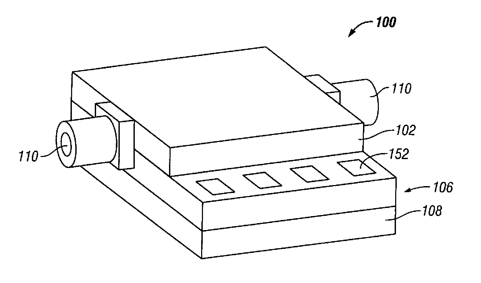
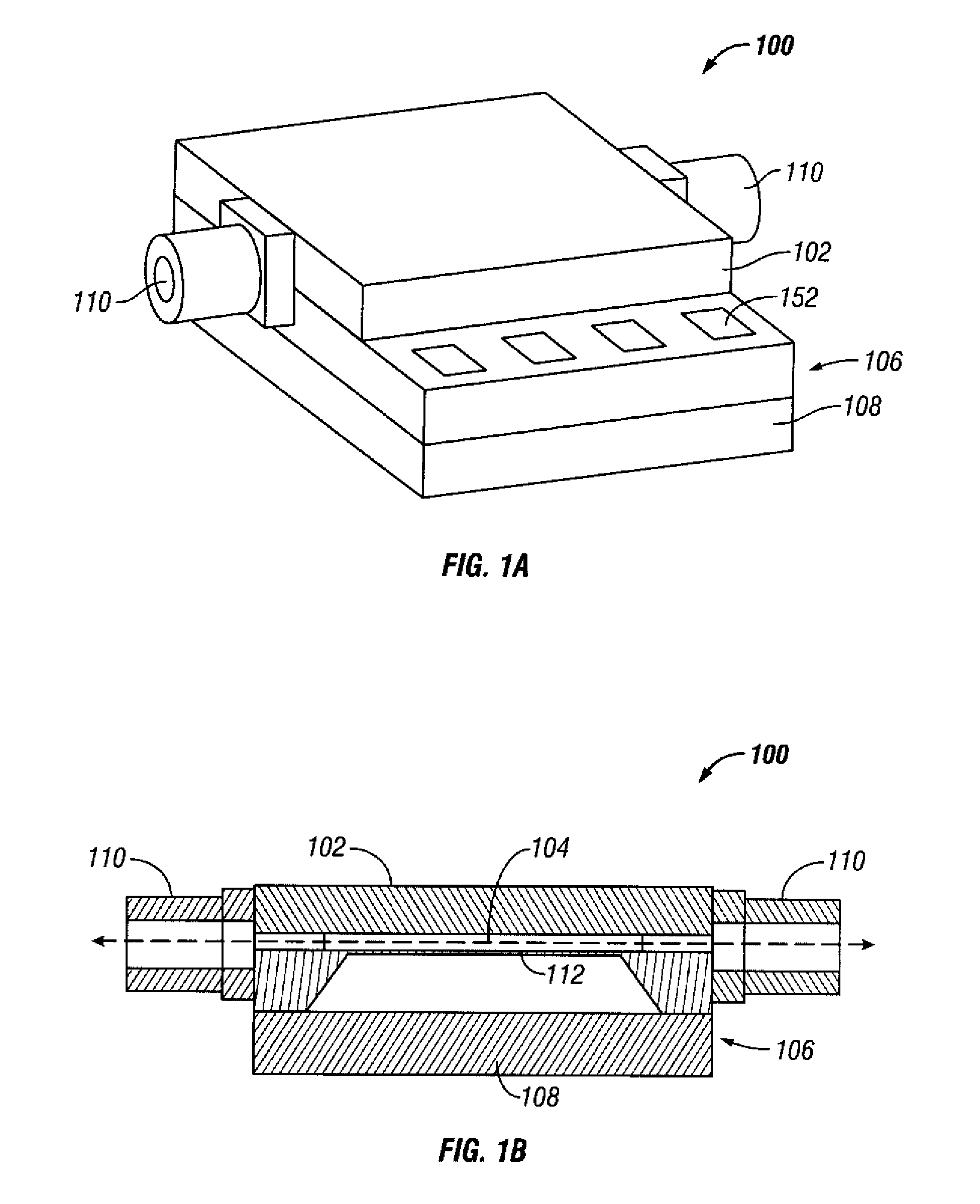
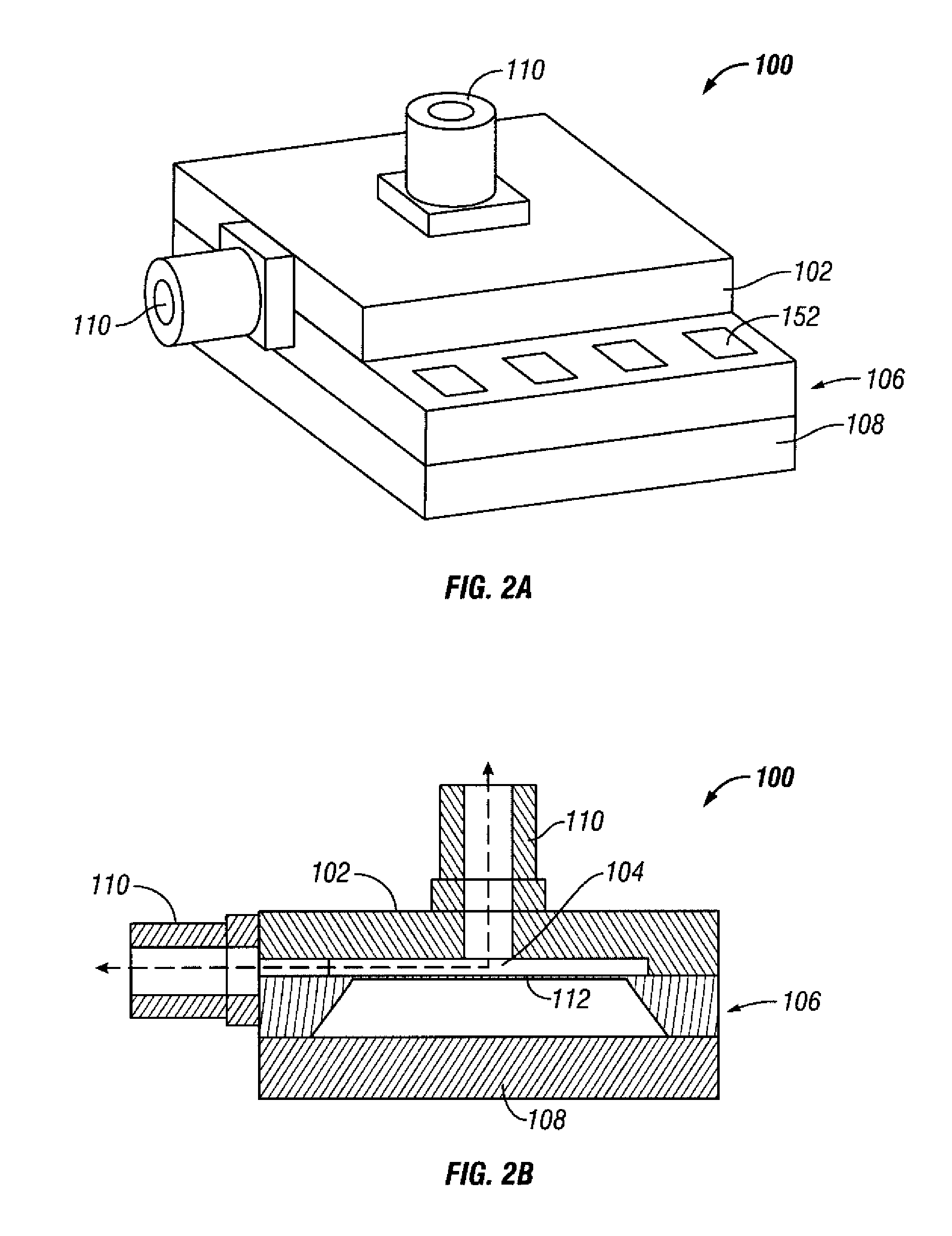
[0025]FIG. 1A illustrates a perspective view of a flow sensor apparatus 100 with ports on sides of a top cap 102 attached to a pressure sensor 106, in accordance with a preferred embodiment. The pressure sensor 106 generally includes a diaphragm 112 attached to a backing plate 108, as shown in FIG. 1B. A cap 102 can be attached to the topside of the pressure sensor 106. A channel 104, as shown in FIG. 1B, can be etched or machined on the cap 102 in order to create a path for fluid flow. The opening and exit of the channel 104 are on the sides of the cap 102. An inlet port and an outlet port 110 can be attached to the opening and exit of the channel 104. The inlet port and the outlet port 110 can be utilized for allowing fluid to pass through therein. Note that as utilized herei...


PUM

PropertyMeasurementUnit
pressureaaaaaaaaaa
electricalaaaaaaaaaa
thermal responseaaaaaaaaaa

Abstract

A flow sensor apparatus that utilizes a pressure sensor with media isolated electrical connections. A cap can be attached to topside of the pressure sensor over a diaphragm to protect bond pads and wire bonds from a fluid media. A flow channel can be etched on the cap with an opening and exit on the sides of the cap so that liquid can flow through the flow channel. An inlet port and an outlet port can be attached to the channel's opening and exit to allow for fluid flow over the diaphragm. The flow channel creates a larger pressure over portions of the diaphragm that increases the deflection of the diaphragm, which increases an output signal of the pressure sensor. V-grooves can be created on two sides of the pressure sensor and in the cap to create the channel for the fluid in and out of the cap's cavity.

Description

[0001]This application is a continuation of U.S. patent application Ser. No. 12 / 273,912 filed Nov. 19, 2008, entitled “FLOW SENSOR APPARATUS AND METHOD WITH MEDIA ISOLATED ELECTRICAL CONNECTIONS”, which is incorporated herein by reference.TECHNICAL FIELD[0002]Embodiments are generally related to sensor methods and systems. Embodiments are also related to flow sensing methods that utilize pressure sensors. Embodiments are additionally related to flow sensor devices that incorporate the use of media-isolated electrical connections.BACKGROUND OF THE INVENTION[0003]Flow sensors can be utilized in many different applications, such as in industrial process control environments, to measure flow rates of process fluids (e.g., liquids and gases) and provide flow signals for flow indicators, controls, and flow volume metering. In majority of micro bridge flow sensors, the open nature of the micro bridge structure can result in condensation from vapor being retained in the micro bridge structu...

Claims


Application Information

Patent Timeline
Patent Type & Authority Applications(United States)
IPC IPC(8): G01L7/00H05K13/00
CPCG01F1/363G01F1/48Y10T29/49826Y10T29/49002G01L19/0023
Inventor MORALES, GILBERTOSTEWART, CARLBECK, SCOTT EDWARDDAVIS, RICHARD ALAN
Owner HONEYWELL INT INC
Why Eureka
Try Eureka