Image processing device
a processing device and image technology, applied in the field of image processing devices, can solve problems such as normal weakness, image shot without blur, and deterioration of shot image, and achieve the effect of reducing the number of images
- Summary
- Abstract
- Description
- Claims
- Application Information
AI Technical Summary
Problems solved by technology
Method used
Image

Examples
first embodiment
[0065]A signal processing unit 1 according a first embodiment of the invention will be explained with referring to figures hereafter. The signal processing unit 1 is an image processing unit used for a consumer camera in the embodiment, but also applied to cameras for other use such as monitoring, TV, a handy video camera and an endoscope, and other devices except cameras such as a microscope, binoculars, and a diagnostic imaging apparatus like imaging with NMR.
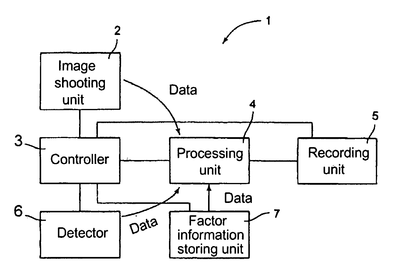
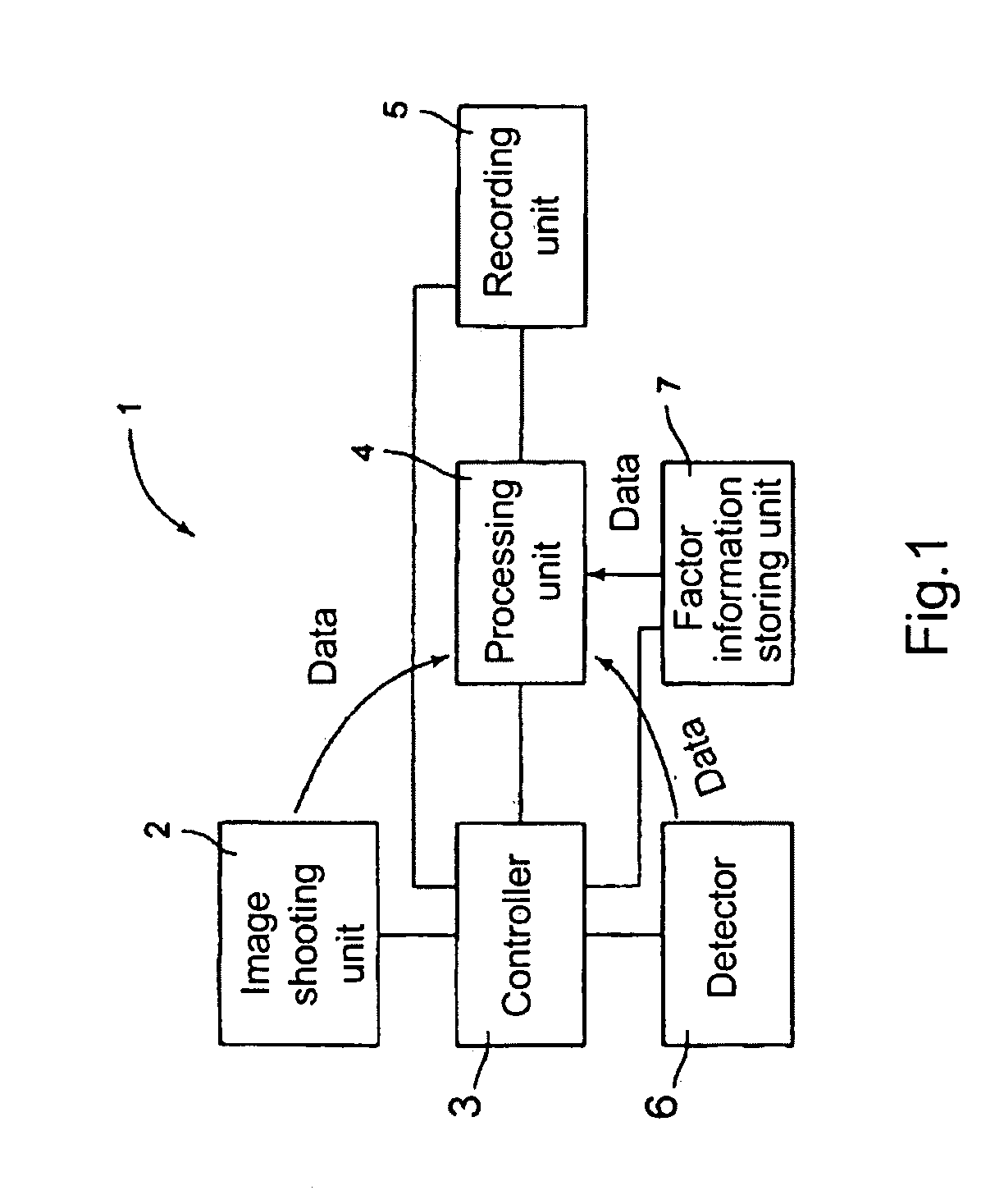
[0066]FIG. 1 shows a brief overview of an image processing device 1. The image processing device 1 comprises an imaging unit 2 for shooting an image such as a figure, a controller 3 for driving the imaging unit 2 and a processing unit 4 for processing an image (signal data) shot by the imaging unit 2. The image processing device 1 further comprises a recording unit 5 for recording an image processed by the processing unit 4, a detector 6 composed of an angular velocity sensor, or the like for detecting fluctuation factor info...
second embodiment
[0101]An image processing unit according a second embodiment of the invention will be explained with referring to FIG. 13 hereafter. The structure of the image processing unit according the second embodiment is the same of the image processing unit 1 according the first embodiment. The same reference numerals of components in the image processing unit 1 according the first embodiment are applied to components in the image processing unit according the second embodiment. Detail explanation of them are simplified or omitted. The reference numeral of the image processing unit according the second embodiment is “1A”. But, the reference numeral “1A” does not appear in the figure.
[0102]Next, a method of restoring an image by the processing unit 4 of the image processing device 1A of the second embodiment will be briefly explained referring to FIG. 13.
[0103]In FIG. 13, definitions of “Io”, “Io′”, “G”, “cImg′”, “γ”, “k”, “nγ”, and “Img” are the same in the first embodiment and explanation o...
third embodiment
[0111]FIG. 14 is a diagram corresponding to FIG. 4(A). A concept of restoring a blurred image by hand jiggling regarding the third embodiment will be explained. If the original image data Img is fluctuated to the initial image data Img′ by the fluctuation-factor information data G, all initial image data Img′ are re-allocated to the restored data region through barycenter value Ga of the point spread function held by the fluctuation-factor information data G as the same filter. This re-allocation makes the restored data Rn existed in the restored region approximated to the primary image data Img.
[0112]The image processing device regarding the third embodiment based on the above concept will be explained referring to FIG. 15. The structure of the image processing unit according to the third embodiment is the same of the image processing units 1 and 1A according first and second embodiments. The same reference numerals of components in the image processing units 1 and 1A according to ...
PUM
 Abstract
Description
Claims
Application Information
 - R&D Engineer
- R&D Manager
- IP Professional
- Industry Leading Data Capabilities
- Powerful AI technology
- Patent DNA Extraction
Browse by: Latest US Patents, China's latest patents, Technical Efficacy Thesaurus, Application Domain, Technology Topic.
© 2024 PatSnap. All rights reserved.Legal|Privacy policy|Modern Slavery Act Transparency Statement|Sitemap