Heat flow sensor

Inactive Publication Date: 2010-08-26
LOZINSKI ALINA +1
View PDF4 Cites 15 Cited by
  • Summary
  • Abstract
  • Description
  • Claims
  • Application Information

AI Technical Summary

Benefits of technology

[0008]The present invention utilizes thermo sensitive elements between all the openings of the sensor, thus enabling the utilization of thermo-sensitive elements, such

Problems solved by technology

As thermo diodes are used, their serial connection accounts for t

Method used


Image

  • Heat flow sensor
  • Heat flow sensor
  • Heat flow sensor

Examples


Embodiment Construction

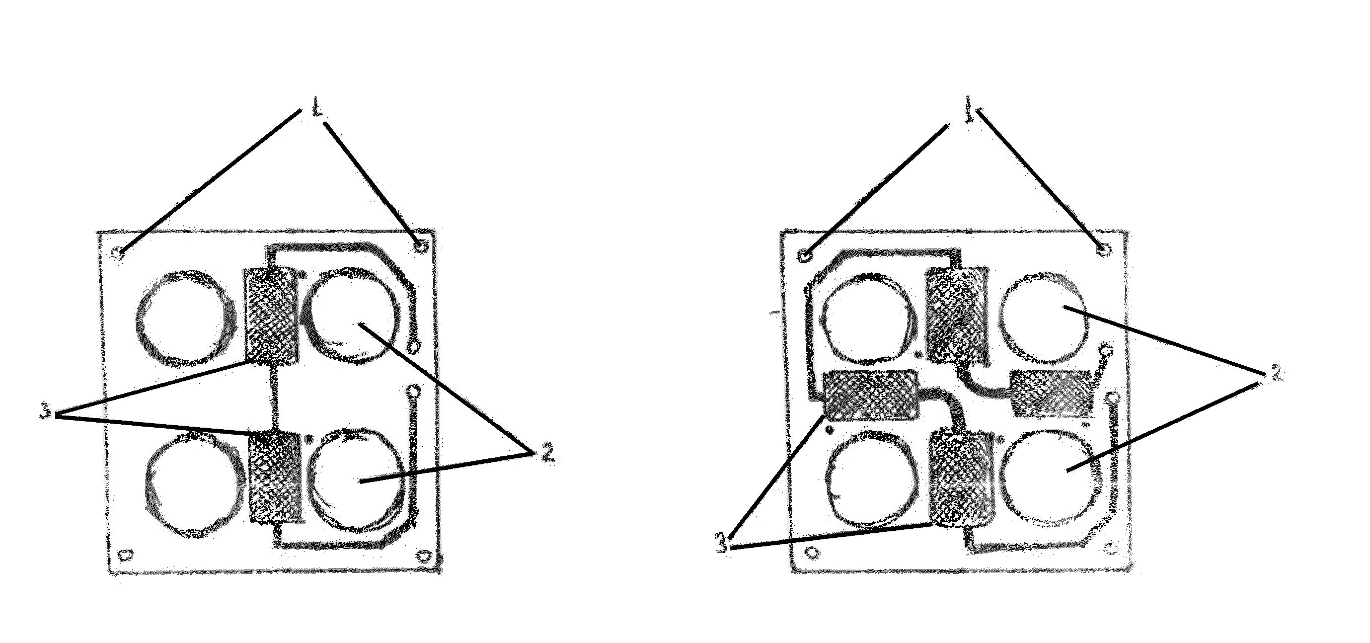
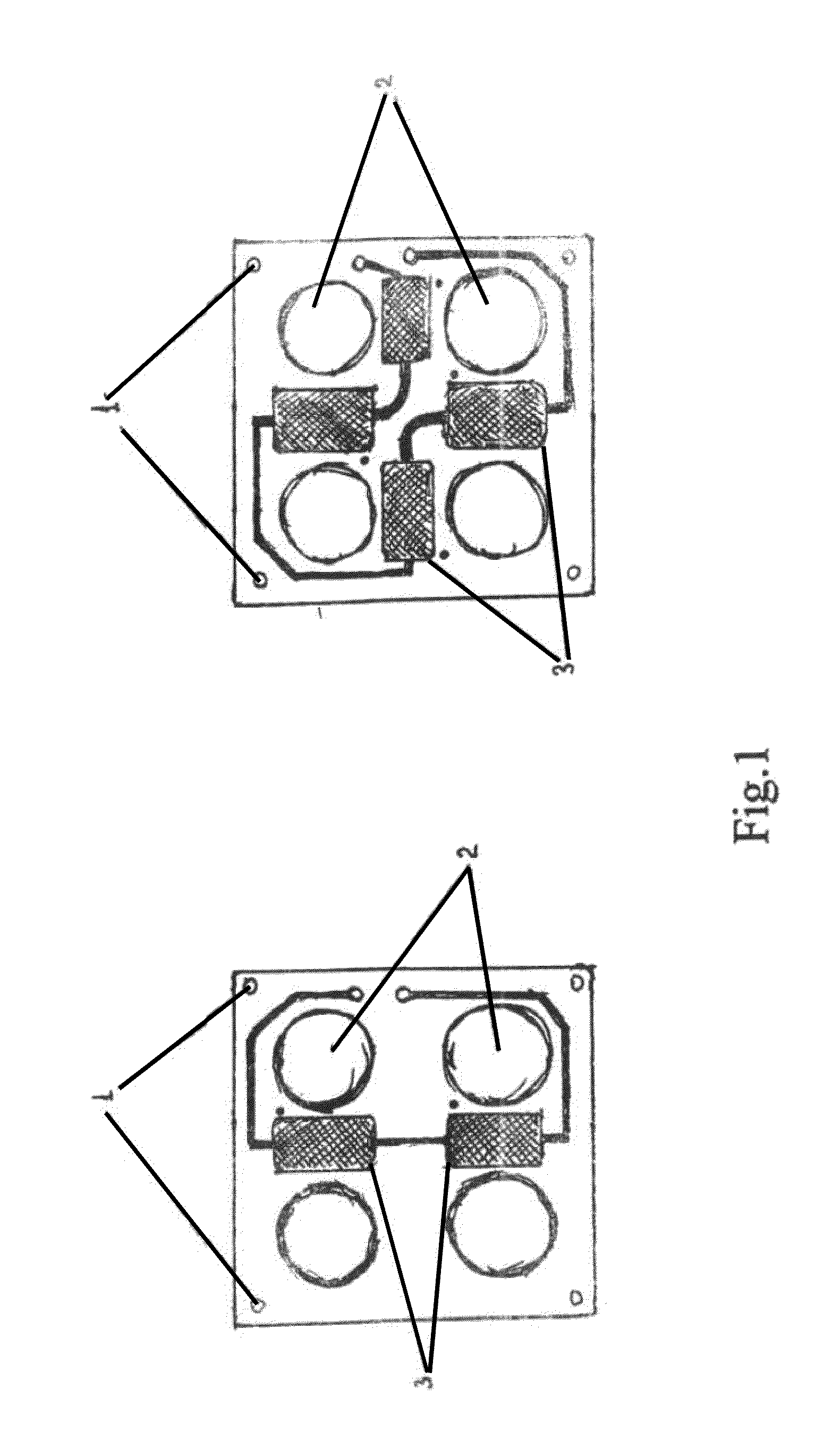
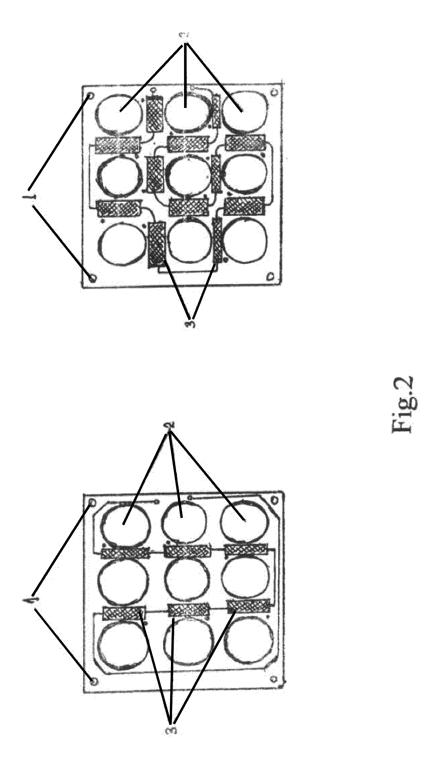
[0016]FIGS. 1, 2 and 3 shows location and connections of thermo-sensitive elements, in prior construction and with our innovations.

[0017]For a rectangular board (mostly used) the maximum number of thermo-sensitive elements is approximately doubled (see #3 in all figures);

[0018]For four openings, 4 instead of 2 thermo sensitive elements may be attached (FIG. 1);

[0019]For nine openings, 12 instead of 6 thermo sensitive elements may be attached (FIG. 2);

[0020]For six openings, 7 instead of 4 thermo sensitive elements may be attached (FIG. 3) and etc.

[0021]For other platform configurations (e.g. round, oval) the number of thermo sensitive elements has also approximately doubled.

[0022]It is desirable to use thermo sensitive elements with the exit wires connected from two opposite sides; if the exit wires of the thermo sensitive elements are located on the same side, one needs to use two sided boards with transient holes.

[0023]In order to use thermo diodes, one needs to observe the polari...


PUM


Abstract

Heat flow sensor having at least two plates with the heat (thermo) sensitive elements and with holes (openings) for the passage of air flow, so that the tops of both plates with the thermo sensitive elements are placed facing the outer surface of the sensor, so that their openings coincide and the construction provides passage of air through the openings whereby the thermo sensitive elements are located between all the holes of the plates and serially connected on every plate, and then the said sensor (plates) has one common point of connection in the middle of each side so that each sensor has at least three output wires—the total, the output of each plate, and therefore the magnitude and direction of the heat flow, are determined by the difference between the outputs of the two earlier described plates.

Description

CROSS-REFERENCE TO RELATED APPLICATIONS[0001]This application claims priority benefit from Israel Patent Application No. 197177, filed Feb. 23, 2009, the contents of which are herein incorporated by reference in their entirety.FIELD OF THE INVENTION[0002]The present invention relates to a sensor for the measurement of heat flowing between an object and the ambient air that may be used in medicine, agriculture, building, and other fields.BACKGROUND OF THE INVENTION[0003]Heat flow sensors and measurements are widely used in medicine, building and agriculture, as described in U.S. Pats. Nos. 4,274,475; 5,524,618; 5,803,915; 6,533,731; 6,595,929 and 7,232,255 and in articles: Heat Flow Sensors, Bulletin 36614, Rdf Corporation. Hudson, New Hampshire, USA; Degenne, M., Klarsfeld, S., in: Building Applications of Heat Flux Transducers, ASTM STP 885, Bales, E., Bomberg, M., Gourville, G. E. (eds.); Philadelfia: American Society for Testing and Materials, 1985, pp 163-171; Heat Flow Sensors ...

Claims


Application Information

Patent Timeline
IPC IPC(8): G01K17/00
CPCG01K17/00
Inventor LOZINSKI, ALINALOZINSKI, YULI
Owner LOZINSKI ALINA
Why Eureka
Try Eureka