Eureka AIR delivers breakthrough ideas for toughest innovation challenges, trusted by R&D personnel around the world.

Wrench with a quickly rotatable driving head

a technology of quick rotatable and driving head, which is applied in the direction of wrenches, screwdrivers, manufacturing tools, etc., can solve the problems of easy elastic fatigue of springs and likely deadlock of steel balls, and achieve quick screwing or unscrewing of thread locking members, simple structure, and easy production and assembly.

Inactive Publication Date: 2012-12-20
CHU CHIN HUI
View PDF9 Cites 1 Cited by
  • Summary
  • Abstract
  • Description
  • Claims
  • Application Information

AI Technical Summary

Benefits of technology

[0006]The objective of this invention is to offer a wrench with a quickly rotatable driving head, able to eliminate the drawbacks of the conventional quick-rotating ratchet wrench that is unsafe in use, difficult in production and assembly and impossible to be used for long.
[0008]In using, when the operating member is pressed to shift downward, the restraining element, which originally pushes against the shallow recess, will be changed to resist against the deep recess of the fixing member to avoid the restraining element being stuck to the restraining member of the handle and enable a user to lift up the handle for disengaging the first positioning portion from the second positioning portion. Thus, the user can directly operate the handle to actuate the driving head to rotate for 360 degrees for quickly screwing or unscrewing a thread locking member. In addition, the fixing member is secured with the second positioning portion of the driving head, while the restraining element is stuck both the shallow recess and the restraining member for restrictedly positioning the operating member on the fixing member. Therefore, when the driving head is operated to rotate quickly, the handle will be restrictedly positioned between the position-limiting portion of the operating member and the restraining member, impossible to separate from the driving head, thus insuring safety in using the wrench of this invention. Furthermore, the wrench with a quickly rotatable driving head in the present invention is restrictedly positioned only by the restraining element that is stuck to both the shallow recess of the fixing member and the restraining member of the handle, simple in structure, easy in production and assembly, low in cost and able to eliminate the defects of the conventional quick-rotating ratchet wrench that employs two steel balls and a spring to make up a quick-disengaging unit. Nevertheless, the steel balls are likely to become deadlocked and the spring is easy to produce elastic fatigue.

Problems solved by technology

Nevertheless, the steel balls are likely to become deadlocked and the spring is easy to produce elastic fatigue.

Method used


Image

  • Wrench with a quickly rotatable driving head
  • Wrench with a quickly rotatable driving head
  • Wrench with a quickly rotatable driving head

Examples


Embodiment Construction

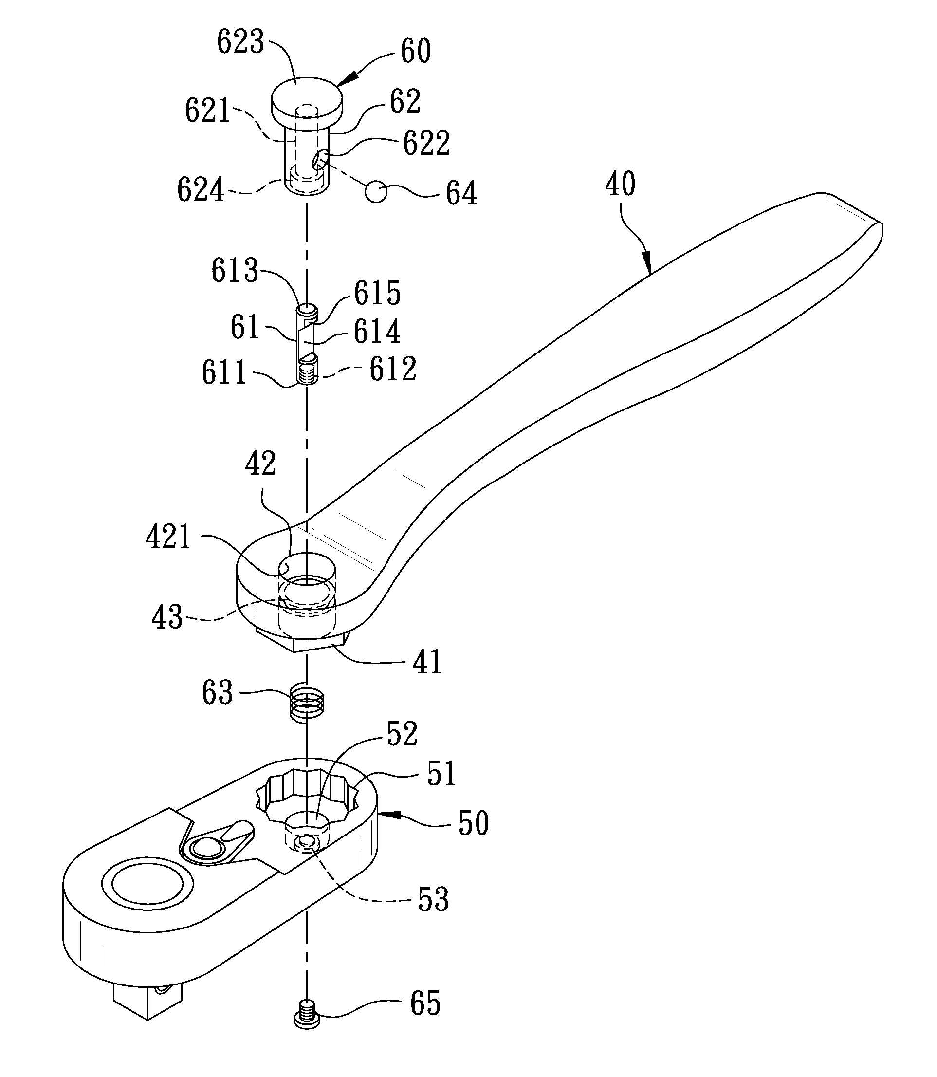
[0019]A preferred embodiment of a wrench with a quickly rotatable driving head in the present invention, as shown in FIGS. 4, 5 and 6, includes a handle 40, a driving head 50 and a quick-disengaging unit 60 as main components combined together.

[0020]The handle 40 has one end provided with a first positioning portion 41 having an insert hole 42 formed with an inner wall 421, which is transversely provided with a restraining member 43. In this preferred embodiment, the first positioning portion 41 is a polygonal protruding block, while the restraining member 43 is an annular projecting edge formed around the inner wall 421 and having an upper annular surface 431 and an opposite lower annular surface 432.

[0021]The driving head 50 has one end formed with a second positioning portion 51 to be correspondingly fitted with the first positioning portion 41 of the handle 40. In this preferred embodiment, the second positioning portion 51 is a polygonal recessed groove. The second positioning ...


PUM


Abstract

A wrench with a quick rotatable driving head includes a handle, a driving head and a quick-disengaging unit. The quick-disengaging unit is composed of a fixing member secured with the driving head, an operating member inserted through the handle and fitted around the fixing member, and a restraining element transversely provided between the fixing member and the operating member and the handle. The handle and the driving head can be separated by the quick-disengaging unit so that the driving head, with the quick-disengaging unit acting as a pivot, can quickly screw or unscrew a thread locking member, and the operating member can be restrictedly positioned on the fixing member by the restraining element, able to prevent the handle and the driving head from separating.

Description

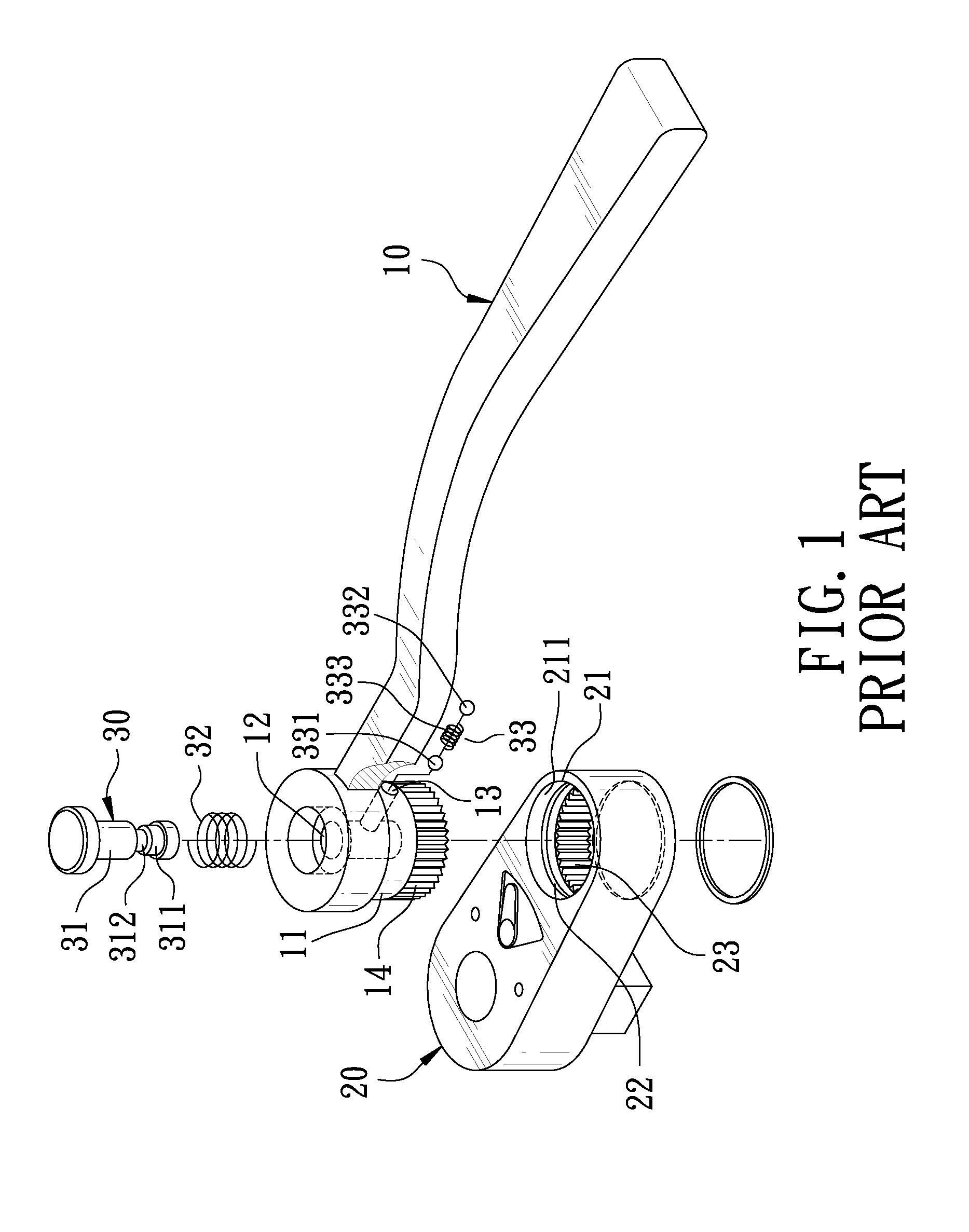
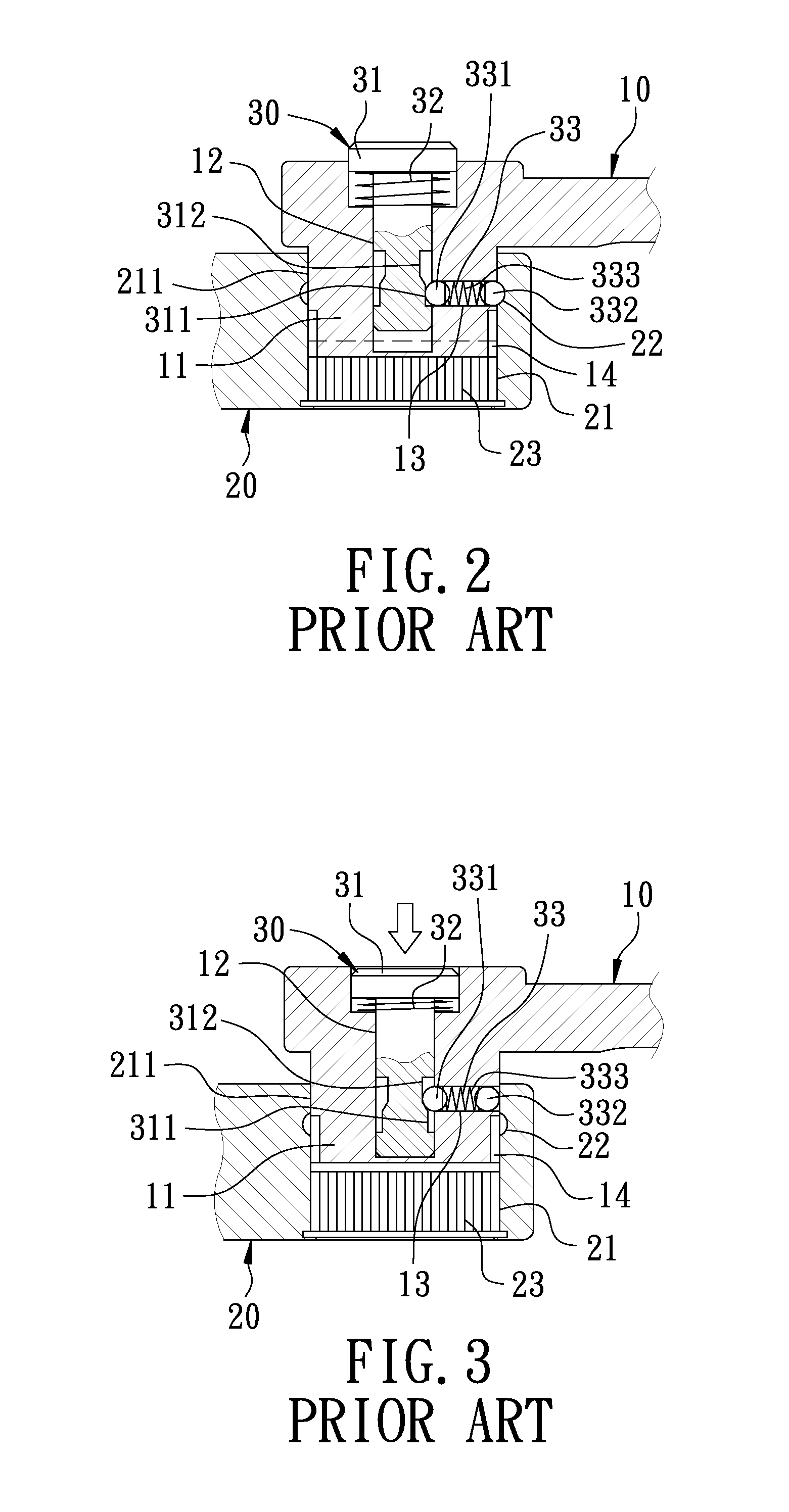
BACKGROUND OF THE INVENTION[0001]1. Field of the Invention[0002]This invention relates to a wrench with a quickly rotatable driving head.[0003]2. Description of the Prior Art[0004]As commonly known, a wrench is employed for screwing or unscrewing a thread locking member (not shown) such as a bolt, and quick-rotating ratchet wrenches have been developed for the convenience of operation. A conventional quick-rotating ratchet wrench, as shown in FIGS. 1, 2 and 3, includes a handle 10, a driving head 20 and a quick-disengaging unit 30 combined together. The handle 10 has one end provided with a bulging block 11 disposed with an insert hole 12 and having a circumferential side bored with a through hole 13 communicating with the insert hole 12 and provided with a first ratchet teeth 14. The driving head 20 is provided with a recessed groove 21 corresponding with the bulging block 11 and formed inside with an inner wall 21, which is provided with an annular recess 22 and second ratchet tee...

Claims


Application Information

Patent Timeline
Patent Type & Authority Applications(United States)
IPC IPC(8): B25B23/16
CPCB25B23/0028B25B13/463
Inventor CHU, CHIN-HUI
Owner CHU CHIN HUI
Why Eureka
Eureka Blog
Learn More