Cable termination system, termination assembly and method for installing such a termination assembly

a technology of cable termination and assembly, which is applied in the direction of cable fittings, cables for removing/armouring cables, electric cable installations, etc., can solve the problems of reducing the concentration of electric field lines between the exposed outer semiconductive layer and the exposed insulating layer through conventional stress members, forming electrical discharges, and insufficient in high or extra high voltage dc applications. , to prevent undesired charge accumulation, the risk of perforation is at least remarkably reduced,

Active Publication Date: 2021-07-06
PRYSMIAN SPA
View PDF17 Cites 1 Cited by
  • Summary
  • Abstract
  • Description
  • Claims
  • Application Information

AI Technical Summary

Benefits of technology

[0020]The Applicant has faced the problem of having a termination provided with an electric field control element power cable capable of significantly controlling the electric field and space accumulation charge for HV or EHV so as to reduce the risk of insulating layer perforation.
[0022]The Applicant has therefore found out that by making an electric field control element provided with semiconducting electrodes and with a field grading layer longitudinally extending between the two semiconducting electrodes and in electric contact therewith it can be possible to prevent undesired charge accumulation as well as high electric field inside the insulating layer.
[0023]Moreover, the combination of semiconducting electrodes and a field grading layer is able to simplify the peeling cable procedures during installation, minimizing possible errors attributable to workers or the like.
[0036]While the field grading layer controls the electric field, the semiconducting electrodes prevent the increasing of the electric gradient around the cable insulating layer, especially at the boundary with the cable outer semiconductive layer. This prevents undesired charge accumulation in the cable insulating layer as well as high electric field inside the cable insulating layer. The risk of perforation is at least remarkably reduced. This enables to use silicone oil as insulating fluid into the insulating tubular body in alternative to SF6.
[0038]In this manner, the second length of exposed outer semiconductive layer provides the electrical connection between the electric conductor and said second semiconducting electrode. Advantageously, it is not necessary to remove the cable outer semiconducting layer up to the length of exposed electric conductor, thereby making the outer semiconducting layer removal, simpler, quicker and cheaper.
[0051]This makes the electric field control element of the invention easy and simple to be manufactured being substantially free from complex geometries that inevitably cause difficulties in the production of the electric field control element and increase its cost.

Problems solved by technology

The Applicant has observed that a reduction of the concentration of the electric field lines between the exposed outer semiconductive layer and the exposed insulating layer through conventional stress member, such as those discussed before, may not be sufficient in high or extra high voltage DC applications.
The Applicant has also observed that one of the most common reasons of terminations failure is due to bad cable peeling operations during installation, which may provoke voids and entrapped air between the insulation layer and the stress member giving rise to the formation of electrical discharges.

Method used


Image

  • Cable termination system, termination assembly and method for installing such a termination assembly
  • Cable termination system, termination assembly and method for installing such a termination assembly
  • Cable termination system, termination assembly and method for installing such a termination assembly

Examples


Embodiment Construction

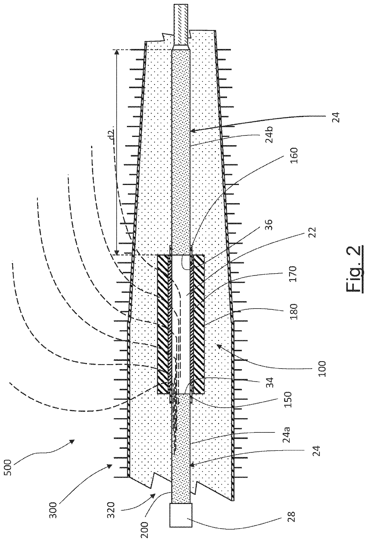
[0073]A terminal 500 for high voltage power cables according to the present invention is shown in FIG. 2.

[0074]In particular, FIG. 2 shows a terminal 500 according to the invention assembled on a HV or EHV power cable 200 which comprises an electric conducting core 20 and a cable insulation system surrounding the electric conducting core 20. The cable insulation system comprises a cable inner semiconductive layer (not illustrated) surrounding and in contact with the electric conducting core 20, a cable insulating layer 22, surrounding and in contact with the respective inner semiconductive layer, and a cable outer semiconductive layer 24, surrounding and in contact with the respective insulating layer 22. Around to the outer semiconductive layer 24 an outer protective sheath 28 is provided which is considered the outermost layer of the cable 200.

[0075]For the purposes of the present invention, since the installation of the terminal 500 requires the cutting and the removal of the out...


PUM


Abstract

The present invention relates to a cable termination system comprising: —a power cable sequentially comprising a first length of exposed outer semiconductive layer, a length of exposed insulating layer and a length of exposed electric conductor, —an electric field control element adapted to be arranged around a portion of said power cable, said electric field control element comprising: —first and second longitudinally spaced semiconducting electrodes; —a field grading layer longitudinally extending between the first and second semiconducting electrodes and in electric contact therewith; —an insulating layer surrounding the semiconducting electrodes and the field grading layer, —wherein the first semiconducting electrode is positioned across a first boundary between the first length of exposed outer semiconductive layer and the length of exposed insulating layer, —wherein said second semiconducting electrode (160) is electrically connected with said length of exposed electric conductor (20), —a tubular insulating body adapted to house said power cable and said electric field control element.

Description

BACKGROUND OF THE INVENTION[0001]The present invention relates to a cable termination system, particular for high (HV) and extra high voltage (EHV) terminations of the fluid-filled type for outdoor use, exposed to air and possible polluting agents. The present invention relates also to a termination assembly and to a method for installing such a termination.[0002]For the purposes of the present invention, with medium and high voltage it is generally meant voltages in a range from 10 kV to 300 kV and more. When the voltage is greater than 300 kV, the expression extra high voltage (EHV) can be used.[0003]For the purposes of the present invention, by termination assembly for power cable it is intended a device suitable to connect an electric cable to a bare conductor, an overhead conductor for example. This termination assembly comprises electrical connecting means between the cable conductor and the bare conductor and electrical separation means between the outer surface of the cable ...

Claims


Application Information

Patent Timeline
Patent Type & Authority Patents(United States)
IPC IPC(8): H02G15/184H02G15/064H02G1/12
CPCH02G15/064H02G1/12H02G15/068
Inventor BOFFI, PAOLOPOGLIANI, STEFANO
Owner PRYSMIAN SPA
Why Eureka
Try Eureka