Driving force generating device

a technology of driving force and generating device, which is applied in the direction of renewable energy generation, vessel construction, greenhouse gas reduction, etc., can solve the problems of limited application of their results, and the risk of assembly breaking or literally blowing away, and achieve the effect of relieving an excessive flow pressur

Inactive Publication Date: 2010-08-26
DOMENECH BARCONS SALVADOR
View PDF10 Cites 17 Cited by
  • Summary
  • Abstract
  • Description
  • Claims
  • Application Information

AI Technical Summary

Benefits of technology

[0035]it balances the kinetic, gravitational and centrifugal forces, minimising the resistances;
[0039]it uses flexible vanes, reducing the effect of possible crashes;
[0046]it does not use rigid blades or profiles, preventing problems due to mechanical stress;

Problems solved by technology

Consequently, the progress can be measured in terms of increase of the quantity and size of the installations, and the efficiency improvements are relatively recent and the application of their results is limited.
In some cases this is obtained thanks to the cinematic resistances inherent to the design, which increases the consequent risk that the assembly breaks or literally blow away.
The cost for starting and keeping this velocity ratio associated with mechanical stress problems due to the different action of the gravitational and centrifugal forces with high velocity ratios can be reasons for not prospering their commercial exploitation.

Method used


Image

  • Driving force generating device
  • Driving force generating device
  • Driving force generating device

Examples


Embodiment Construction

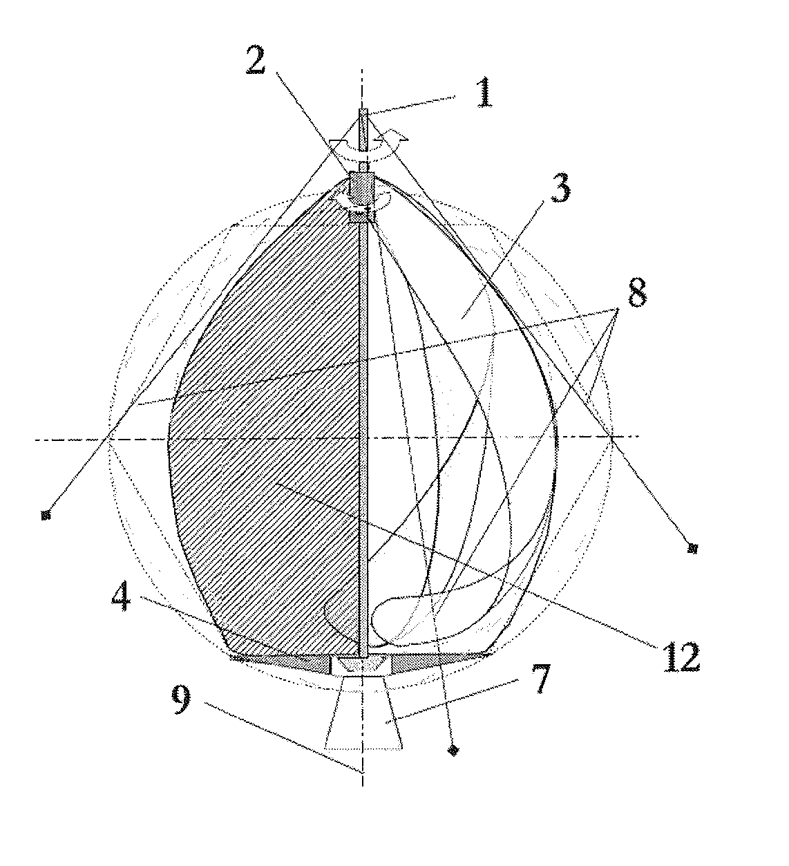
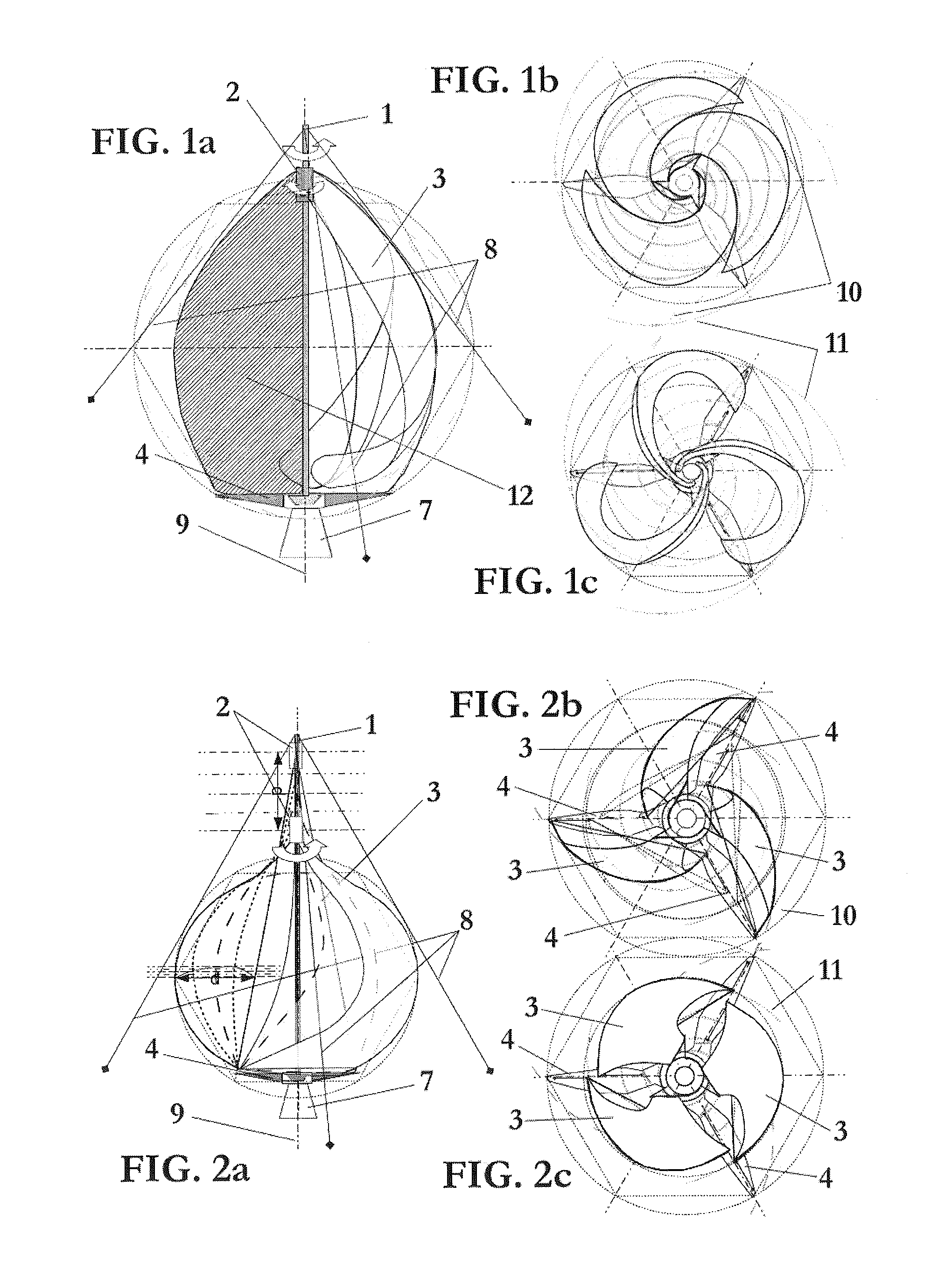
[0063]The device of the present invention comprises a column 1 that is sized to hold the element assembly that form the device and to transmit motive power to rotating radial rods 4 placed at the lower part of the column 1.

[0064]This column 1 comprises a head 2 that is rotatable about the column 1 and movable along said column 1.

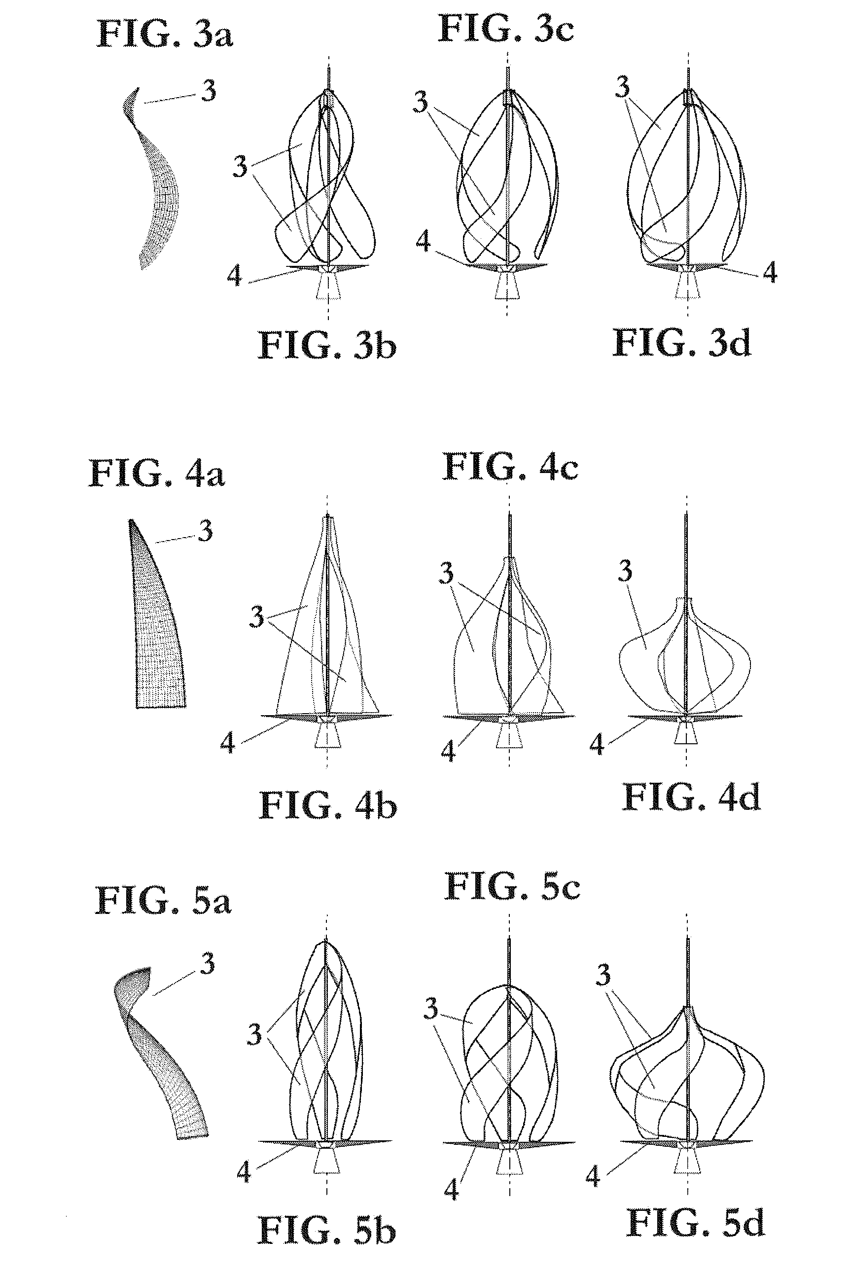
[0065]The device of the present invention also comprises a plurality of aerodynamic membranes 3, preferably flexible, that are joined, each one, by its upper end to said head 2 and by its lower end to one of said radial rods 4.

[0066]The movement of the head 2 and of the radial rods 4 facilitated the continuous and isometric transformation of the membranes 3, whose winding results in revolution geometries of catenary kind.

[0067]Controlling the positioning of the head 2 and the membranes 3 the thrust forces (flow, gravitational, centrifugal and friction) are affected, from which interaction results a rotating component and another one according to the transfor...


PUM


Abstract

The invention relates to a driving force generating device including a column (1) provided with a plurality of flexible elements (3) positioned around the column (1), which react in response to the flow by rotating positively in the same direction. The invention is characterised in that the flexible elements take the form of aerodynamic membranes (3), the arrangement and shape of which correlate with logarithmic spiral patterns. The invention is also characterised in that it includes a movable head (2) positioned in the upper part of the central column (1) and a base (4) positioned in the lower part of said column (1), the upper part of each membrane (3) being secured to the movable head (1) and the lower part of each membrane being secured to the base (4). The invention can be used to balance kinetic, gravitational and centrifugal forces, thereby minimising resistance.

Description

[0001]The present invention refers to a device for generating driving force, and particularly to a generator of driving force that use the energy of a fluid flow.BACKGROUND OF THE INVENTION[0002]The objective of the traditional devices for generating driving force, such as mills, rotors and turbines, is to use the dynamic energy that concentrate air, water and other fluids to generate mechanical and electromotive forces. The force that these devices can produce depends on the volume, mass and velocity of the fluids they operate with, so that it increases or decreases directly with the scale, i.e. the flap or cross area, and it depends at cube with respect to the velocity of the operating fluid.[0003]This fact explains that, even though the mills and turbines have been used from long time ago, its operation was based on exploiting flows with high energy (water falls, windy zones). Consequently, the progress can be measured in terms of increase of the quantity and size of the installa...

Claims


Application Information

Patent Timeline
Patent Type & Authority Applications(United States)
IPC IPC(8): F03D7/04F04D29/38
CPCF03D3/061F05B2240/311F05B2240/93F05B2210/16Y02E10/74F03D13/25Y02E10/727
Inventor DOMENECH BARCONS, SALVADOR
Owner DOMENECH BARCONS SALVADOR
Why Eureka
Try Eureka