Damper device, high pressure pump having the same and manufacturing method of the same
a technology of damper device and high pressure pump, which is applied in the direction of machines/engines, liquid fuel engines, positive displacement liquid engines, etc., can solve the problems of affecting the manufacturing cost of the damper device, and the volume of the damper chamber of the damper member may change,
- Summary
- Abstract
- Description
- Claims
- Application Information
AI Technical Summary
Benefits of technology
Problems solved by technology
Method used
Image
Examples
first embodiment
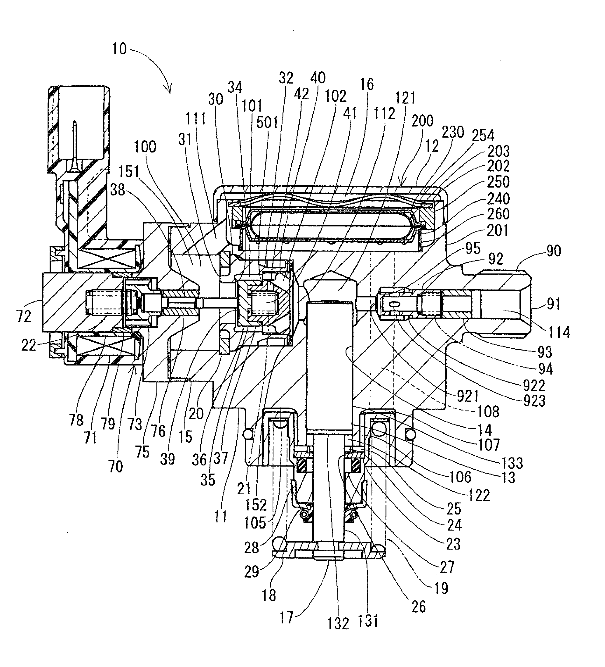
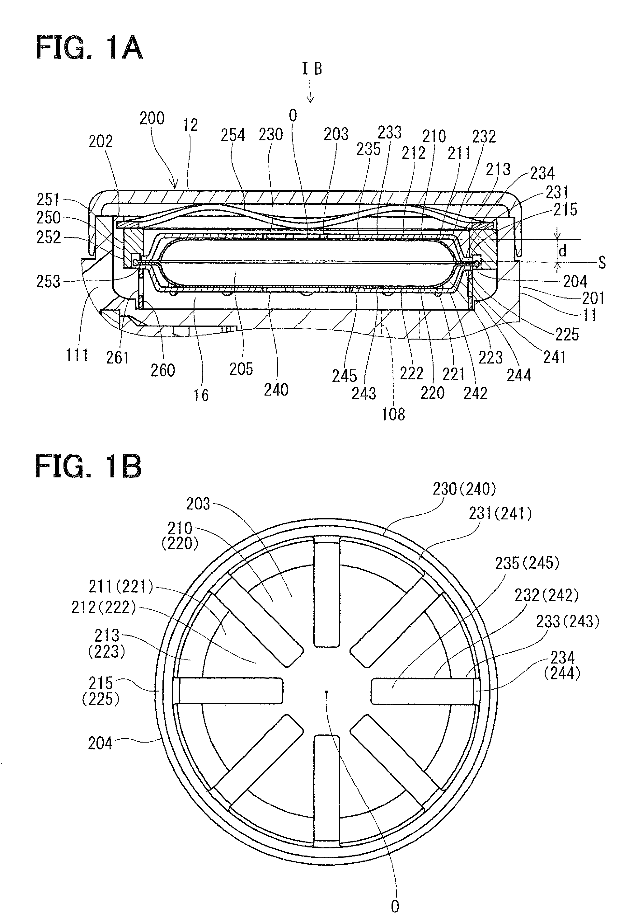
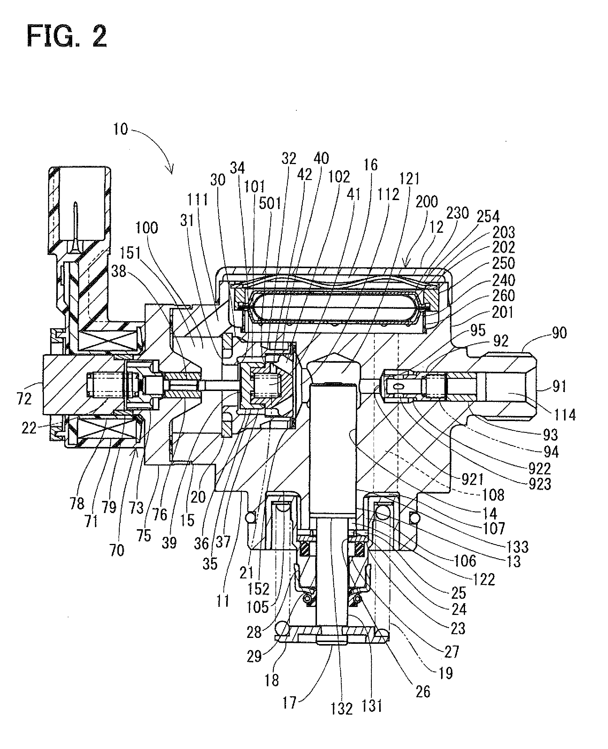
[0034]In a first embodiment of the present invention, a damper device is implemented in a high pressure pump of a vehicle. The high pressure pump supplies fuel to, for example, an injector of a diesel engine or a gasoline engine of a vehicle through a delivery pipe. As shown in FIG. 2, the high pressure pump 10 includes a housing 11, a plunger 13, a valve body 30, a valve member 35, an electromagnetic drive device 70 and the damper device 200.
[0035]The housing 11 is made of metal, such as stainless steel. The housing 11 forms a cylinder 14. The plunger 13 is supported in the cylinder 14 of the housing 11 in such a manner that the plunger 13 is axially reciprocatable in the cylinder 14.
[0036]The housing 11 forms a guide passage 111, an intake passage 112, a pressurizing chamber 121 and a delivery passage 114. The housing 11 has a tubular portion 15. The tubular portion 15 forms a passage 151, which communicates between the guide passage 111 and the intake passage 112. The tubular por...
second embodiment
[0106]FIG. 7 shows a portion of a high pressure pump according to a second embodiment of the present invention. In the second embodiment, the shapes of the first and second-side cover members 330, 340 are different from those of the first embodiment.
[0107]In the second embodiment, the first-side cover member 330 is formed by processing a sheet of metal, such as stainless steel having a predetermined rigidity through press working process or bending process. The first-side cover member 330 includes a first-side outer peripheral portion 331 and a first-side limiting portion 332. The first-side outer peripheral portion 331 is configured into a generally annular form, and the first-side limiting portion 332 radially inwardly extends from the first-side outer peripheral portion 331. In the present embodiment, the first-side limiting portion 332 is configured to radially inwardly extend from the first-side outer peripheral portion 331 and to cover the first-side concave portion 211 of the...
third embodiment
[0111]FIGS. 8A and 8B show a portion of a high pressure pump according to a third embodiment of the present invention. In the third embodiment, the shapes of the first and second-side support members are different from those of the first embodiment.
[0112]As shown in FIG. 8A, the first-side support member 350 includes a tubular portion 351, a top surface portion 352 and a small diameter tubular portion 353. The tubular portion 351 is configured into a generally cylindrical tubular form. The top surface portion 352 is configured into a generally annular form and radially inwardly extends from one end part of the tubular portion 351. The small diameter tubular portion 353 is configured into a generally cylindrical tubular form and extends from an inner peripheral edge part of the top surface portion 352 in a direction opposite from the tubular portion 351. As discussed above, the first-side support member 350 is configured into the generally cylindrical tubular form.
[0113]Furthermore, ...
PUM
| Property | Measurement | Unit |
|---|---|---|
| Pressure | aaaaa | aaaaa |
Abstract
Description
Claims
Application Information
 - R&D
- Intellectual Property
- Life Sciences
- Materials
- Tech Scout
- Unparalleled Data Quality
- Higher Quality Content
- 60% Fewer Hallucinations
Browse by: Latest US Patents, China's latest patents, Technical Efficacy Thesaurus, Application Domain, Technology Topic, Popular Technical Reports.
© 2025 PatSnap. All rights reserved.Legal|Privacy policy|Modern Slavery Act Transparency Statement|Sitemap|About US| Contact US: help@patsnap.com


