Method, system and model for indirect bonding
- Summary
- Abstract
- Description
- Claims
- Application Information
AI Technical Summary
Benefits of technology
Problems solved by technology
Method used
Image

Examples
first embodiment
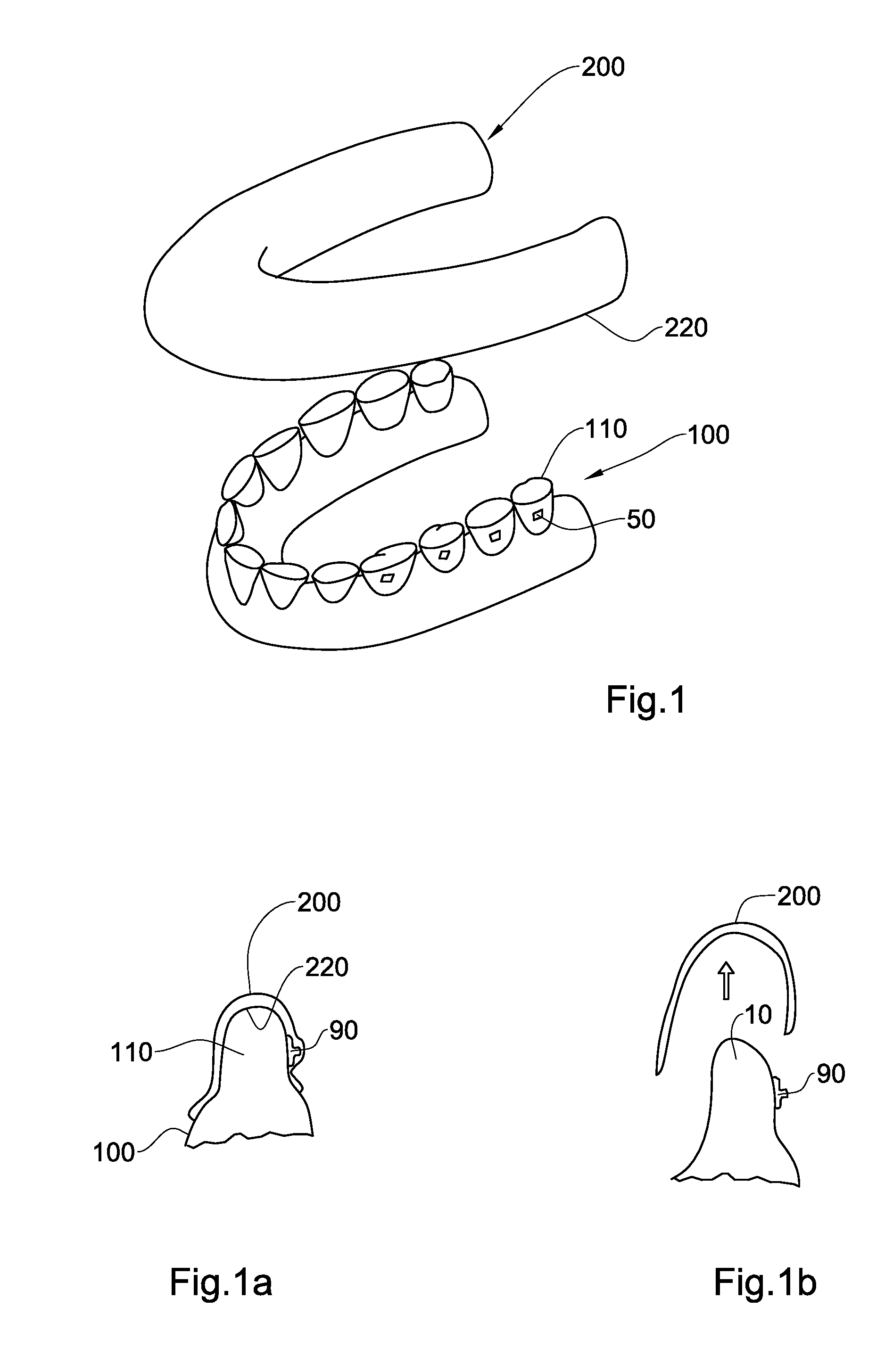
[0060]Referring to FIG. 1, the present invention comprises a physical model of a tooth arch, generally designated with numeral 100, comprising a plurality of dental appliance targets 50, also referred to interchangeably herein as targets 50.
[0061]In this embodiment, the model 100 is a physical replica, made from a suitable material as is known in the art, representing the real tooth arch of a patient regarding which it is desired to provide an orthodontic treatment to at least some of the teeth therein. In alternative variations of this embodiment, the model may instead be a physical replica of part of an arch, for example representing a number of teeth or even representing one tooth of the dentition of the patient.
[0062]One or more than one target 50 is provided on the representation of a respective tooth model 110 in the model 100, each at a position relative to the dental surfaces of the respective tooth model 110 that is considered to provide the required orthodontic treatment f...
second embodiment
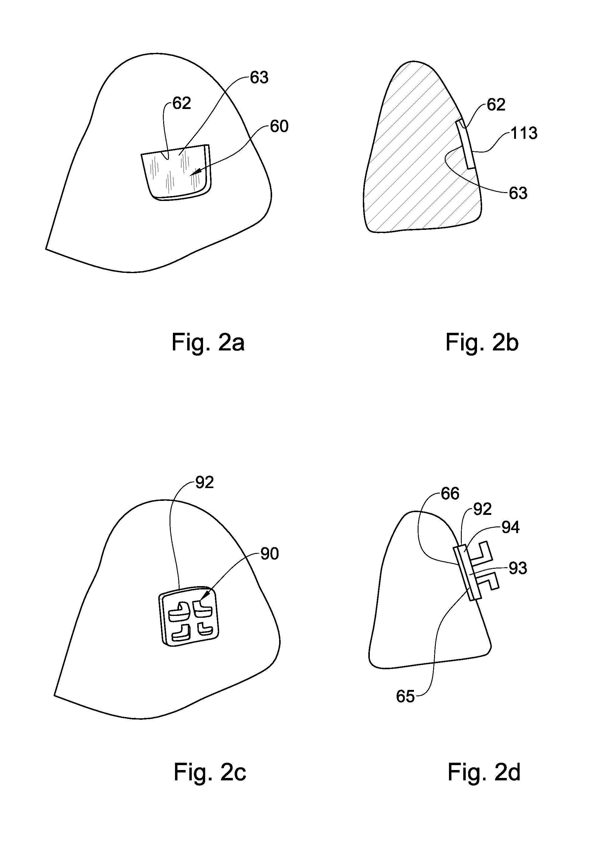
[0101]Thus, according to one aspect of the second embodiment, the targets 50 are in the form of a physical marking that is engraved, scratched or otherwise formed as a depression into the surface of the tooth model 100.
[0102]Alternatively, according to another aspect of the second embodiment, rather than providing a physical mark as an indentation into the surface of the physical model, the targets 50 in the second embodiment and variations thereof may be provided as optical marks, which are characterized as having a different color and / or contrast or other optical property with respect to the rest of the surface of the physical model 100, in particular the respective tooth model 110 thereof, without necessarily providing a physical mark that is engraved or otherwise physically projecting into the surface of the tooth model. Thus, such targets 50 can be printed, drawn, painted, colored or otherwise provided on the surface of the tooth model 110, similar to the notches and other phys...
third embodiment
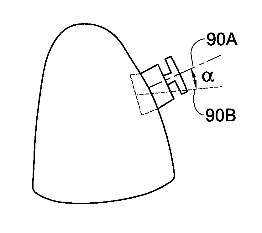
[0129]In a variation of the third embodiment, and referring to FIGS. 10a to 10d, recess 700 comprises all the elements and features of recess 600 of the embodiment of FIGS. 9a to 9d, with the following differences. In the embodiment of FIGS. 10a to 10d, the recess 700 has a shoulder 720 and base 710, rather than providing visual or physical clues for aligning the orthodontic appliance 90 along direction 625, a mechanical stop 750 is provided, protruding from the base 710, and an edge 92a adjacent to edge 92 is abutted onto the stop 750, thereby constraining the orthodontic appliance 90 onto the tooth model 110 in all degrees of freedom. It is to be noted that in this embodiment, stop 750 has height, width and depths dimensions that are within the envelope defined by the imaginary surface 117 of the tooth model 110 that was removed to form the recess base 710 and shoulder 720. Thus, for example, the stop 750 may be manufactured in a machine removal operation while making the recess 7...
PUM
 Abstract
Description
Claims
Application Information
 - R&D
- Intellectual Property
- Life Sciences
- Materials
- Tech Scout
- Unparalleled Data Quality
- Higher Quality Content
- 60% Fewer Hallucinations
Browse by: Latest US Patents, China's latest patents, Technical Efficacy Thesaurus, Application Domain, Technology Topic, Popular Technical Reports.
© 2025 PatSnap. All rights reserved.Legal|Privacy policy|Modern Slavery Act Transparency Statement|Sitemap|About US| Contact US: help@patsnap.com