Radio transmission device, radio reception device, cell switching method, and radio communication system

a radio transmission device and cell technology, applied in the direction of electrical equipment, wireless communication, etc., can solve the problem of increasing the load on the radio channel, and achieve the effect of effectively utilizing resources and preventing the amount of signaling accompanying cell switching from increasing

Inactive Publication Date: 2010-08-26
PANASONIC CORP
View PDF3 Cites 65 Cited by
  • Summary
  • Abstract
  • Description
  • Claims
  • Application Information

AI Technical Summary

Benefits of technology

[0022]According to the present invention, it is possible to effectively utilize resources of a unicast / MBMS mixed cell and prevent the amount of signaling accompanying cell switching from increasing.

Problems solved by technology

That is, when different communication terminals receive information transmitted from a base station in a streaming service and so forth using one dedicated channel respectively, if the number of communication terminals that desire to receive the information increases, the load on the radio channel increases.

Method used


Image

  • Radio transmission device, radio reception device, cell switching method, and radio communication system
  • Radio transmission device, radio reception device, cell switching method, and radio communication system
  • Radio transmission device, radio reception device, cell switching method, and radio communication system

Examples


embodiment 1

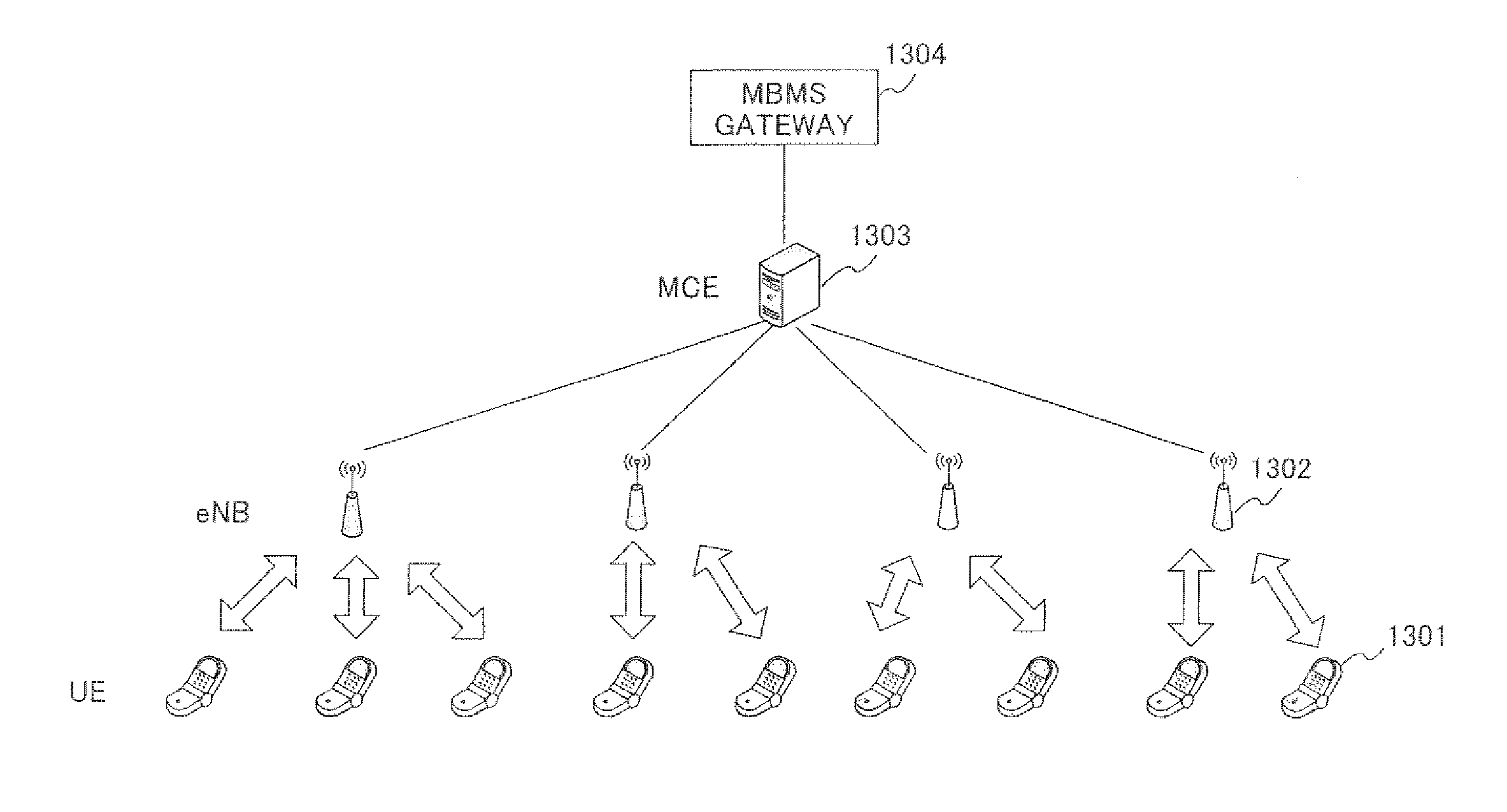
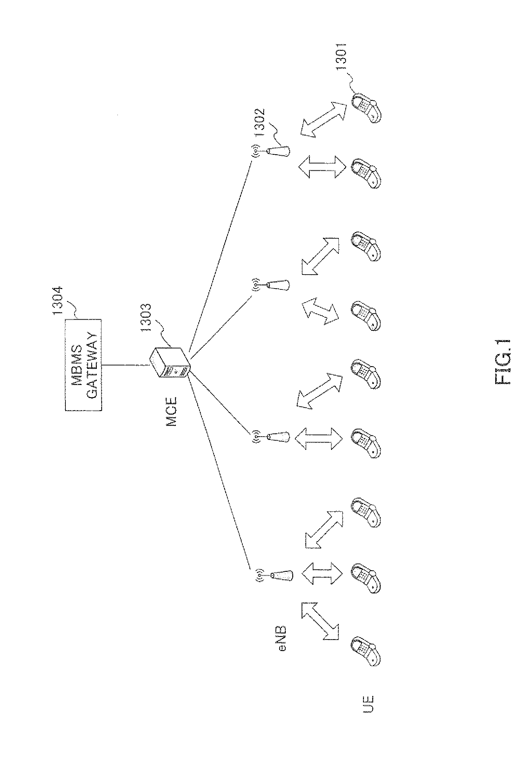
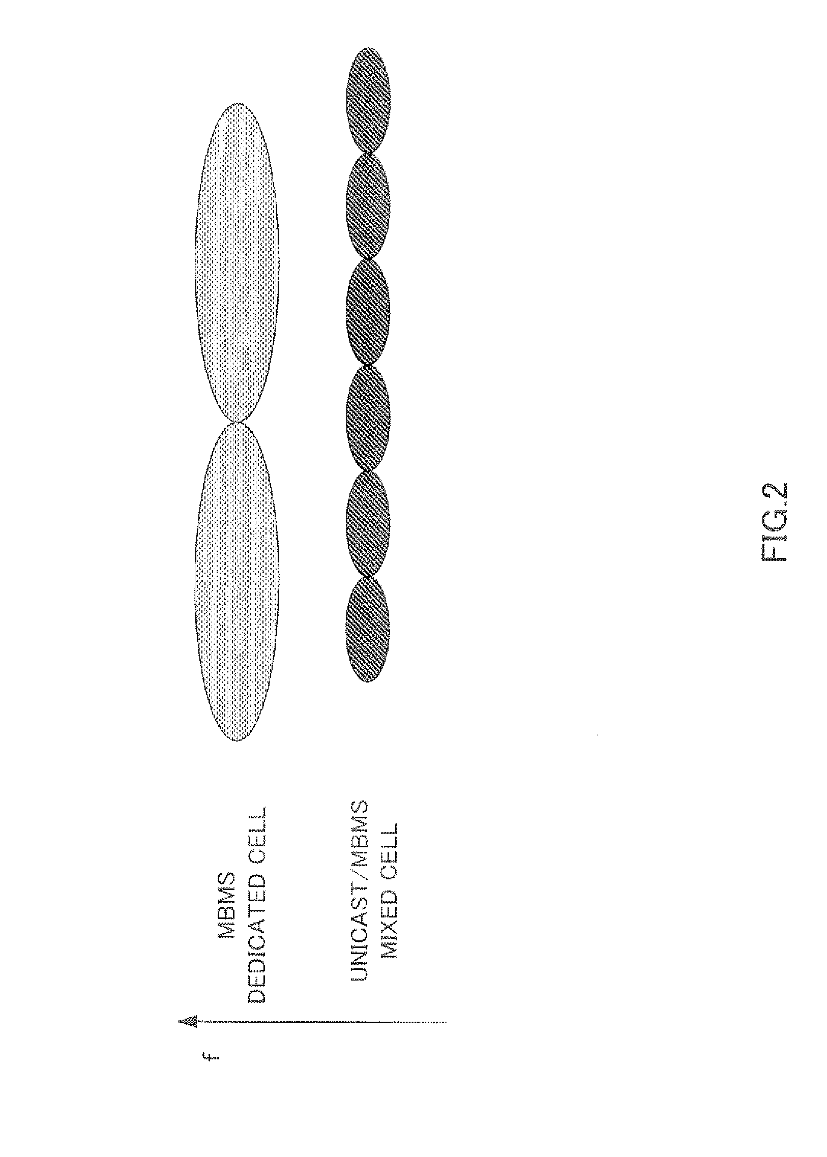
[0040]Operations of the UE according to embodiment 1 of the present invention to switch a serving MBMS cell will be described using FIG. 4. First, suppose the UE receives an MBMS service from an MBMS dedicated cell using the MBMS dedicated cell as a serving MBMS cell (ST 101 and ST 102). Furthermore, the UE camps on a unicast / MBMS mixed cell and receives system information from an eNB of the unicast / MBMS mixed cell (ST 103).

[0041]Here, when a request for arrival of a voice call to the UE is made, a base station in the unicast / MBMS mixed cell belonging to a tracking area with which the UE is registered transmits paging (calling) (ST 104).

[0042]System information, paging and so forth is received for a period (gap) during which MBMS data is not being transmitted while the UE is receiving an MBMS service from the MBMS dedicated cell.

[0043]Since the UE does not camp on the MBMS dedicated cell, the UE need not perform cell reselection in the MBMS dedicated cell. Therefore, no parameter fo...

embodiment 2

[0068]Although a case has been described in embodiment 1 where switching between the MBMS dedicated cell and the unicast / MBMS mixed cell is performed based on threshold judgment on the reception level of the MBMS dedicated cell with a first threshold and a second threshold resulting from adding an offset value to the first threshold, a timing of switching a serving MBMS cell will be described in embodiment 2 of the present invention.

[0069]When there is a difference between a MBMS data transmission timing and a serving MBMS cell switching timing, the UE may not be able to receive MBMS data and the MBMS data may be lost. Thus, to prevent this data loss, the period after the reception level of the MBMS dedicated cell is lower than the first threshold until the UE starts switching the serving MBMS cell or the period after the reception level of the MBMS dedicated cell is higher than the second threshold until the eNB commands the UE to switch the serving MBMS cell, is set. This period i...

embodiment 3

[0087]FIG. 12 is a conceptual diagram illustrating an area configuration according to embodiment 3 of the present invention. Here, suppose a unicast / MBMS mixed cell (hereinafter referred to as “macro cell”) and an indoor unicast / MBMS mixed cell having a small cell radius (hereinafter referred to as “indoor cell”) are arranged on the same frequency. Since both the macro cell and the indoor cell are unicast / MBMS mixed cells, both an uplink and a downlink exist. In this case, operations of the UE to switch the serving MBMS cell will be described using FIG. 13.

[0088]First, suppose the UE receives an MBMS service from the macro cell using the macro cell as the serving MBMS cell (ST 101 and ST 102). In the present embodiment, since both the macro cell and the indoor cell are unicast / MBMS mixed cells, the UE can camp on both cells.

[0089]The UE receives a parameter used for a threshold for switching the serving MBMS cell through system information of the macro cell (ST 1001). In the present...


PUM


Abstract

It is possible to provide a radio transmission device, a radio reception device, and a radio communication system which can effectively use a resource of a unicast / MBMS cell and prevent increase of a signaling amount accompanying a cell switching. A UE measures a reception level of an MEMS-dedicated cell. When the measured reception level is below a first threshold value, the UE switches the serving MBMS cell from the MBMS-dedicated cell to the unicast / MBMS cell. Moreover, when the reception level of the MBMS-dedicated cell exceeds a second threshold value obtained by adding an offset value to the first threshold value, the serving MBMS cell is switched from the unicast / MBMS cell to the MBMS-dedicated cell.

Description

TECHNICAL FIELD[0001]The present invention relates to a radio transmitting apparatus, radio receiving apparatus, cell switching method and radio communication system.BACKGROUND ART[0002]In the field of mobile communication, in recent years, technological studies on a multimedia broadcast / multicast service (hereinafter referred to as “MBMS”), which is a broadcasting service or multicast service, are underway. MBMS is not one-to-one communication but one-to-multiple communication and one base station transmits the same data to a plurality of communication terminals simultaneously.[0003]Advantages of MBMS are as follows. That is, when different communication terminals receive information transmitted from a base station in a streaming service and so forth using one dedicated channel respectively, if the number of communication terminals that desire to receive the information increases, the load on the radio channel increases. On the other hand, when MBMS is used, even when the number of...

Claims


Application Information

Patent Timeline
Patent Type & Authority Applications(United States)
IPC IPC(8): H04W24/00
CPCH04W72/085H04W72/005H04W72/30H04W72/542
Inventor ISHIDA, CHIEAOYAMA, TAKAHISA
Owner PANASONIC CORP
Why Eureka
Try Eureka