
V-ribbed belt having an outer surface with improved coefficient of friction

a v-ribbed belt and outer surface technology, applied in the direction of driving belts, mechanical equipment, vehicles/pulley ropes, etc., can solve the problems of rotational slippage, noise generation of v-ribbed belts, etc., to improve the friction coefficient, reduce noise, and reduce slippage

Active Publication Date: 2010-08-26
DAYCO IP HLDG
View PDF10 Cites 15 Cited by
  • Summary
  • Abstract
  • Description
  • Claims
  • Application Information

AI Technical Summary

Benefits of technology

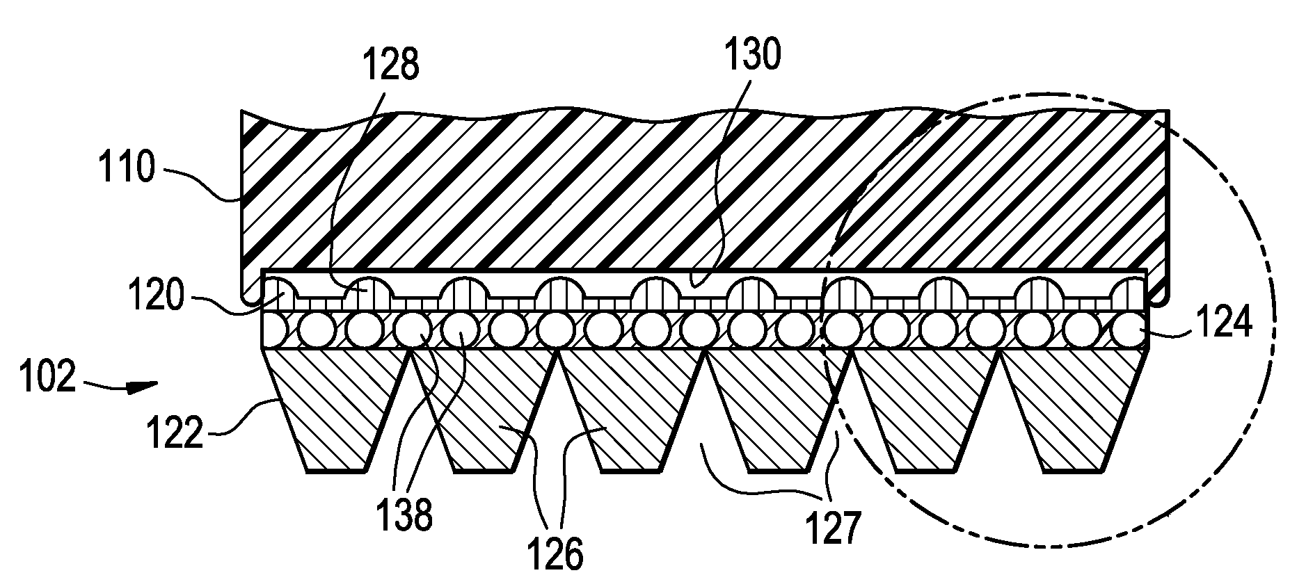
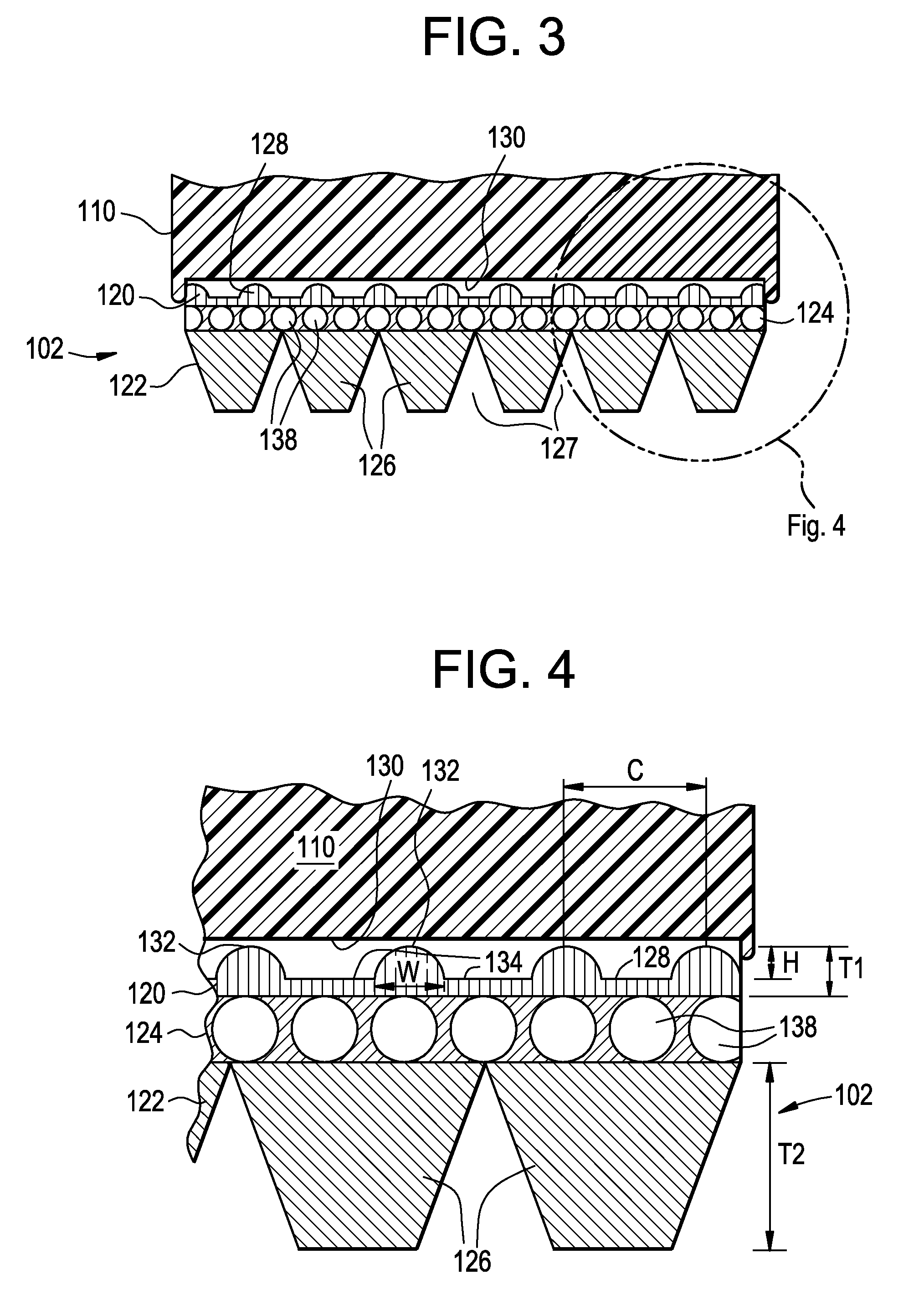
[0008]The disclosed back-side section of the V-ribbed belt has an improved coefficient of friction which efficiently drives a flat-faced back-side pulley, which may be used to operate accessories in an engine. The back-side section with its raised features and low regions also reduces noise and provides a means to remove debris and fluids away from the back-side section to back-side pulley interface. Debris and fluids could lead to slippage of the belt against the pulley; and hence, the disclosed embodiments reduce slippage. Additionally, the disclosed back-side section has a long belt life and during that life maintains an effective coefficient of friction when against a flat-faces back-side pulley.

Problems solved by technology

In operation, there is a tendency for V-belts and V-ribbed belts to emit noise; a common complaint, especially on automotive drives.
Belt noise is predominately the result of pulley engagement and disengagement noise arising as the ribs on the belt enter into and exit from the pulley grooves or arising from excessive rotational slip of the pulley relative to the belt.
Rotational slip occurs during rapid acceleration or deceleration of the drive such as is encountered during shifting, engine startup or engine shutdown or due to excessive loading or insufficient wrapping around the pulleys.

Method used


Image

  • V-ribbed belt having an outer surface with improved coefficient of friction
  • V-ribbed belt having an outer surface with improved coefficient of friction
  • V-ribbed belt having an outer surface with improved coefficient of friction

Examples


Embodiment Construction

[0019]The preferred embodiments of the improved V-ribbed belt are described below with reference to the accompanying figures. While the various features of this invention are hereinafter illustrated and described with reference to the figures, it is to be understood that the invention is broader in scope and not limited to just those embodiments that are pictured.

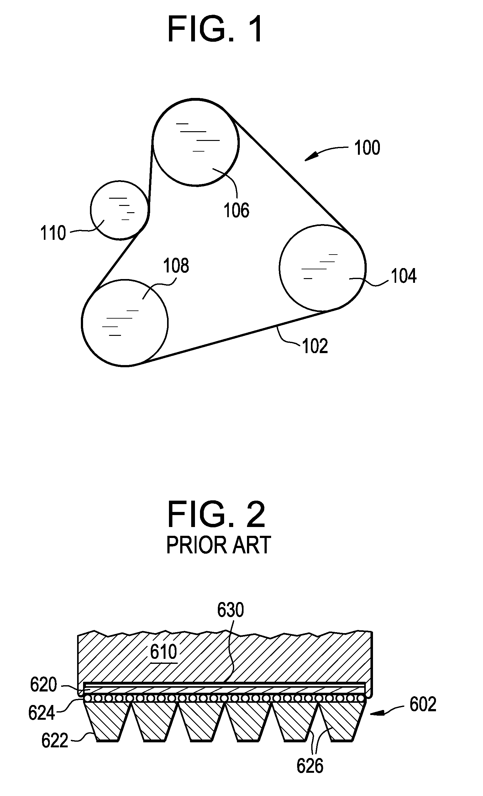
[0020]Referring to FIG. 1, a serpentine belt drive system, generally designated 100, may include a V-ribbed belt 102, a front-side driver pulley 108, one or more driven front-side accessory pulleys 104,106, and one or more back-side pulleys 110. The drive system 100 depicted in FIG. 1 is only one example of a drive system configuration. Many alternate arrangements are known in the art and are suitable for use with the present invention.

[0021]FIG. 2 depicts, in cross-section, the engagement between a conventional V-ribbed belt 602 and a conventional back-side pulley 610. The conventional V-ribbed belt includes an inner front...


PUM

PropertyMeasurementUnit
Lengthaaaaaaaaaa
Lengthaaaaaaaaaa
Fractionaaaaaaaaaa

Abstract

A V-ribbed belt for a mechanical power transmission is disclosed. The V-ribbed belt comprises an outer back-side surface, an inner front-side surface, and a load-carrying section disposed between the front-side and back-side surfaces. The front-side surface includes a plurality of laterally spaced longitudinally extending v-ribs. The back-side surface includes a plurality of raised features that, when running on a flat-faced, back-side pulley, form a contact patch of about 20% to about 50% of that of a traditional flat-faced belt running on a flat-faced pulley. The reduced contact patch provides increased contact pressure which in turn provides an improved effective coefficient of friction between the belt and the pulley.

Description

BACKGROUND[0001]This invention relates to power transmission belts and, more particularly, to an improved V-ribbed belt having an outer back-side surface with a high coefficient of friction for driving flat-faced back-side pulleys.[0002]V-belts and V-ribbed belts are used in a wide range of environments. V-ribbed belts are preferred for their high power transmission capability, which is attributable to the large contact area between the ribs on the belt and the flank on the cooperating pulleys.[0003]In operation, there is a tendency for V-belts and V-ribbed belts to emit noise; a common complaint, especially on automotive drives. Belt noise is predominately the result of pulley engagement and disengagement noise arising as the ribs on the belt enter into and exit from the pulley grooves or arising from excessive rotational slip of the pulley relative to the belt. Rotational slip occurs during rapid acceleration or deceleration of the drive such as is encountered during shifting, eng...

Claims


Application Information

Patent Timeline
IPC IPC(8): F16G5/00
CPCF16G5/20F16G7/00F16G9/00F16G9/04
Inventor WESTELAKEN, PAUL M.
Owner DAYCO IP HLDG
Learn More