In service support center and method of operation

a technology of vehicle support and service support, applied in the field of vehicle fleet maintenance, can solve the problems of no data collection, trending or aggregating of manually collected information, and inability to correlate data, so as to increase the awareness of fleet managers and reduce life cycle costs

Inactive Publication Date: 2010-08-26
BAE SYST INFORMATION & ELECTRONICS SYST INTERGRATION INC
View PDF0 Cites 27 Cited by
  • Summary
  • Abstract
  • Description
  • Claims
  • Application Information

AI Technical Summary

Benefits of technology

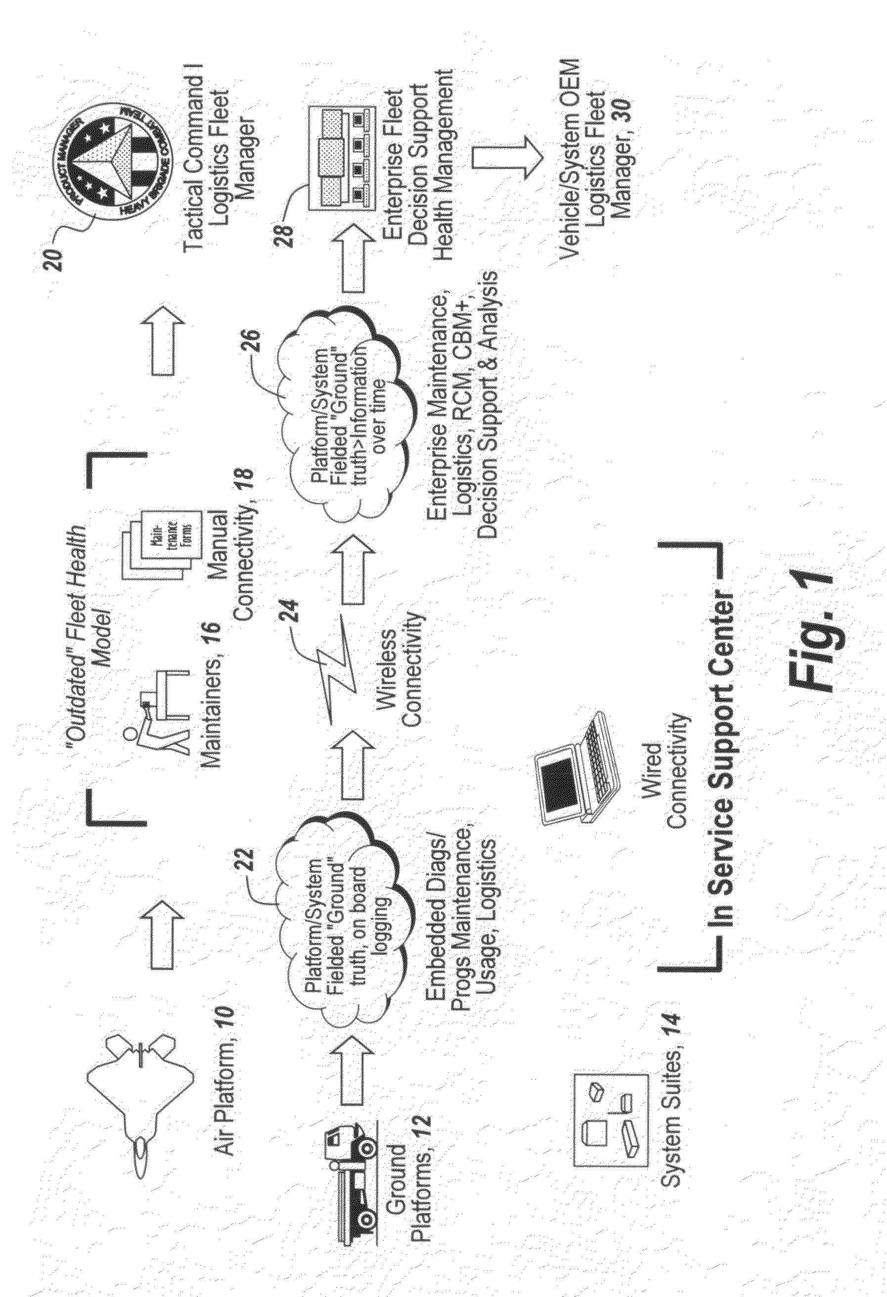
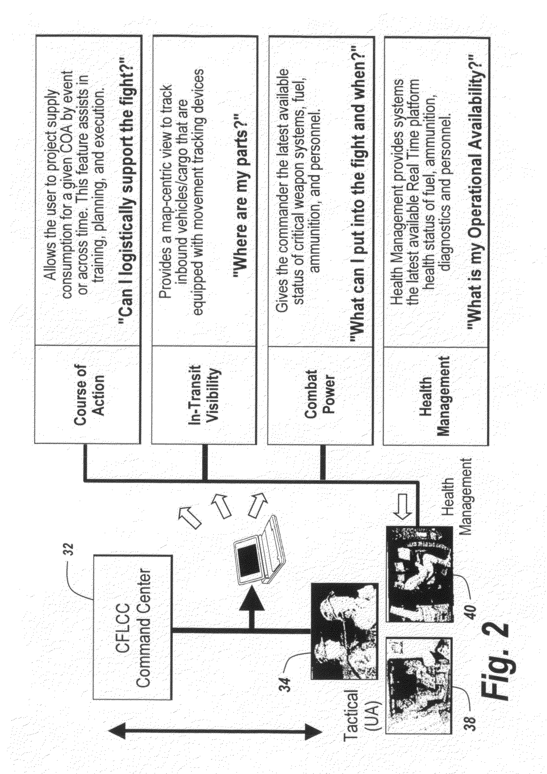
[0016]The present invention involves an In Service Support Center (ISSC) which is provided with the core capabilities necessary for information collection, provides a depository, and includes an analysis and assessment system. This system is adapted to use all available automated and manual means of data collection from ground vehicles, personnel, and at strategic information points. The subject in service support center employs a collection of tools and services described in the associated Conception of Operation (CONOPS) document provides. These tools thus enable the development of higher level information intelligence and situational awareness / assessment over time so as to provide an overall support system, increase fleet manager awareness, and reduce life cycle costs associated with sustaining a fleet. In one embodiment of the subject invention the support center provides a centralized database to obtain, process, and store vehicle maintenance and support information.

Problems solved by technology

The disadvantages of such systems were that there was little or no correlation of data across multiple data sources, with attendant inaccurate or non-existent data collection.
Moreover, these systems performed no analysis, trending or aggregation of the manually-collected information.
Since the vast majority of older military vehicles have very little embedded diagnostics, the existing paper systems to detect and troubleshoot these vehicles do not live up to modern requirements.
Thus, given the fact that the state of the vehicle health monitoring for most military vehicles is antiquated, especially for Line Replaceable Units (LRUs) that are taken off the vehicle, checked and replaced at a depot, there is very little information that can be put into a database over time to deduce what the real failures are in the field, for instance failure mode of the LRU that was pulled.
In short, there is no capability presently for the development of a longer term strategy, or for the generation of deductions based on trend analysis.
Thus, at present there is no way to develop statistics that relate to the inherent reliability of the fielded systems.
As a result, maintenance ground truth for maintenance events were not regularly inputted into any maintenance management system.
Thus, one could not for instance update trouble shooting manuals effectively by drawing upon an organized and accurate database of all field failure root causes, or for calling upon any diagnostic system and maintenance systems or effectiveness procedures.
In short, there was no mechanism whereby all the data collected over time for very specific vehicles, for instance the Bradley Fighting Vehicles, was available to make inroads into more effective maintenance, support system optimization or to provide any cost savings.
However, even if data was brought to the same place for analysis, the information is typically never shared with contractors or those responsible for optimization and maintenance.
There is, for instance, “no evidence of failure found” data available from prior systems and this has cost the US Army upwards of millions of dollars over a period of years, just for the one major tactical vehicle in the fleet.
This is because there has been no off-board enterprise system which provides and integreates services for performing reliability center maintenance, diagnostic / prognostic growth support, total asset visibility, condition-based maintenance, trend analysis and data collection.
Thus, for instance the government is never able to truly solve a large number of the vehicle performance issues that would lead to decreasing the maintenance timeline from days needed to be able to fix a vehicle in hours.
Thus, heretofore there has been no centralized system for solving reliability improvement problems.

Method used


Image

  • In service support center and method of operation
  • In service support center and method of operation
  • In service support center and method of operation

Examples


Embodiment Construction

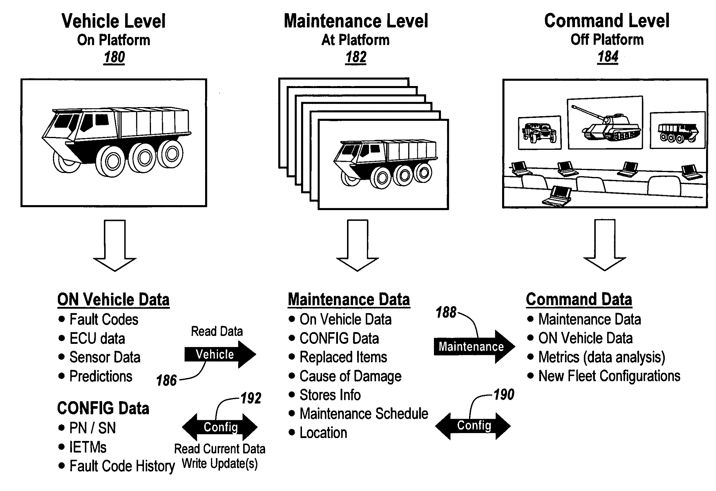
[0028]Before describing the drawings, the present invention provides a support center which identifies the core capabilities necessary for an information collection, depository, analysis and assessment system, using all available automated and manual means of data collection from ground vehicles, personnel, and at strategic information points. The subject support center involves a collection of tools and services that enables the development of higher level information intelligence and situational awareness / assessment over time so that the overall supportability system, fleet manager awareness, and life cycle costs associated with sustaining a fleet are continuously improved.

[0029]In the context of functional capabilities, a centralized database is provided to obtain, process and store information and present it to stakeholders.

[0030]Those skilled in the art will appreciate that various tools may be used in the efficient practice of this invention. Reliability Centered Maintenance (...


PUM


Abstract

In a method for in service support for a vehicle fleet wherein the improvement comprises providing Reliability Centered Maintenance (RCM), Conditioned Based Maintenance (CBM), Fleet Management (FM), Vehicle / Component Asset Tracking, Stores / Consumable Inventory, and maintenance management.

Description

RELATED APPLICATIONS[0001]This application claims rights under 35 USC §119(e) from U.S. Application Ser. No. 61 / 154,595 filed Feb. 23, 2009, the contents of which are incorporated herein by reference.FIELD OF THE INVENTION[0002]The present invention relates to vehicle fleet maintenance and more particularly to an off-platform vehicle support center.BACKGROUND OF THE INVENTION[0003]In the prior art manual data collection and forms have been used by maintenance personnel and / or vehicle field service representatives. This data was accumulated in multiple disparate data bases both within the Department of Defense and within industry data collection facilities. The disadvantages of such systems were that there was little or no correlation of data across multiple data sources, with attendant inaccurate or non-existent data collection. Moreover, these systems performed no analysis, trending or aggregation of the manually-collected information.[0004]By way of background, the U.S. Army Vehic...

Claims


Application Information

Patent Timeline
Patent Type & Authority Applications(United States)
IPC IPC(8): G06Q10/00
CPCG06Q10/0631G06Q10/087G06Q10/08G06Q10/06313
Inventor DICKSON, RICHARD G.WAGNER, RONALD E.WOEHL, RICHARD A.
Owner BAE SYST INFORMATION & ELECTRONICS SYST INTERGRATION INC
Why Eureka
Try Eureka