
Reciprocating Saw Blade With Tangs On Each End And Related Method

a saw blade and tang technology, applied in the field of saw blades, can solve the problems of significant wear life remaining, portion of the blade may not be worn out, and the blade typically incurs the most wear and/or wear, and achieves the effect of improving the wear li

Active Publication Date: 2010-09-02
BLACK & DECKER INC
View PDF17 Cites 59 Cited by
  • Summary
  • Abstract
  • Description
  • Claims
  • Application Information

AI Technical Summary

Benefits of technology

[0023]One advantage of the present invention is when the primary cutting portion of the reciprocating saw blade (i.e., the inner portion of the reciprocating saw blade adjacent to the chuck or shoe of the reciprocating saw) wears faster than the outer or free end of the reciprocating saw blade, the reciprocating saw blade may be removed from the chuck, flipped or rotated 180°, and the other tang inserted into the chuck to present a relatively fresh primary cutting portion of the same blade. As a result, the blades of the present invention can achieve significantly improved wear life in comparison to prior art reciprocating saw blades. This is particularly advantageous for reciprocating saw blades with relatively expensive elongated cutting edges, such as reciprocating saw blades with carbide and / or diamond grit cutting edges.

Problems solved by technology

Because most workpieces are relatively small as compared to typical reciprocating saw blades, and because the length of each saw blade stroke is relatively short (typically about ¾ inch to about 1¼ inches), reciprocating saw blades typically incur most wear and / or wear out along a primary cutting surface defined by the inner end of the cutting edge adjacent to the foot or shoe.
As a result, it is frequently necessary to discard a reciprocating saw blade that is worn out only along the inner portion of the blade, whereas the outer portion of the blade may not be worn out at all and / or may have significant wear life remaining.
This problem can be particularly acute in connection with relatively expensive blades, and / or blades made with relatively expensive cutting edge materials, such as reciprocating saw blades with carbide and / or diamond grit cutting edges.
However, short blades have limited capabilities as they are not well suited to handle large workpieces.
As a result, reciprocating saw users may be required to obtain multiple blades of differing lengths to suit particular workpiece restraints, thereby increasing costs and requiring more frequent blade changes.

Method used


Image

  • Reciprocating Saw Blade With Tangs On Each End And Related Method
  • Reciprocating Saw Blade With Tangs On Each End And Related Method
  • Reciprocating Saw Blade With Tangs On Each End And Related Method

Examples


Embodiment Construction

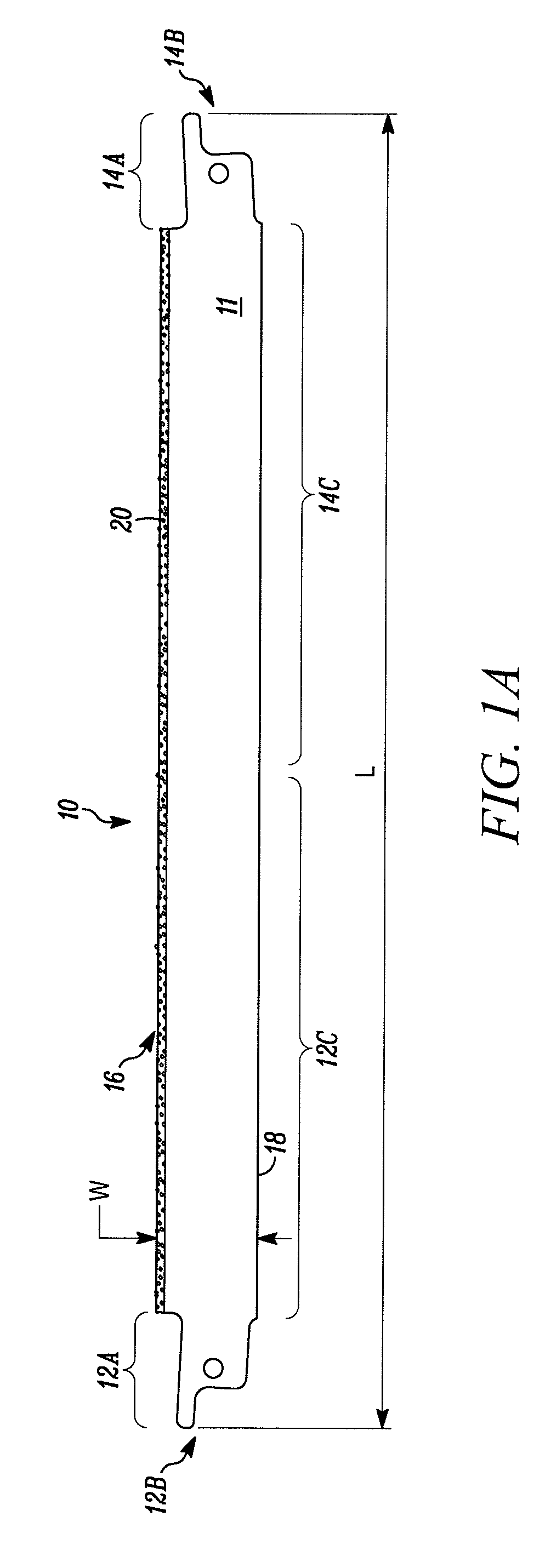
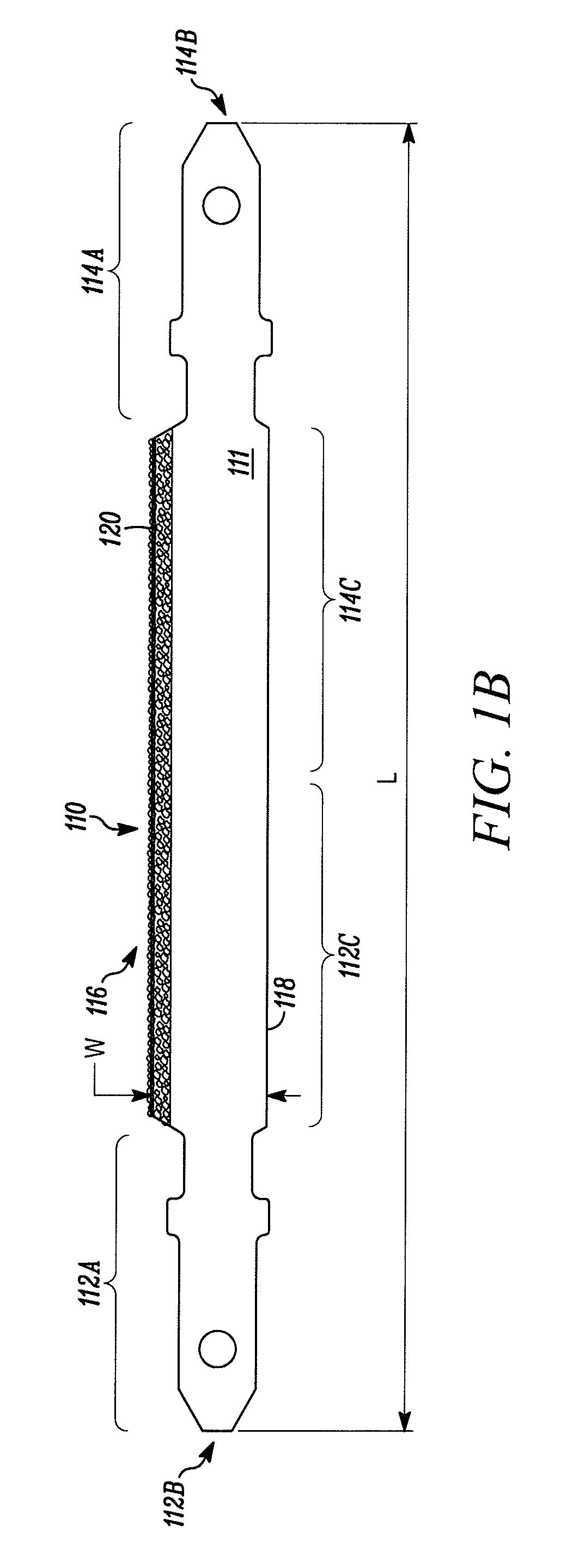
[0036]Referring to the drawings and, in particular, FIG. 1, a reciprocating saw blade with a tang at each end in accordance with an illustrative embodiment of the of the present invention is shown and generally represented by the reference numeral 10. As indicated above, a reciprocating saw is a hand-held saw that includes a chuck or like mechanism for releasably engaging a saw blade and driving the saw blade in a reciprocating motion, such as a jig saw or a recip saw. The reciprocating saw causes the saw blade 10 to move in a reciprocating motion in an a series of push and pull strokes, i.e., forward strokes and return strokes. During each stroke, the saw blade 10 moves between a rearmost position and a forwardmost position to, in turn, apply a cutting action to a workpiece. When the reciprocating saw blade 10 is engaged by a reciprocating saw chuck at one end of the blade, the opposite end of the blade defines a free end that is allowed to move into engagement and through a workpi...


PUM

PropertyMeasurementUnit
Timeaaaaaaaaaa
Widthaaaaaaaaaa

Abstract

A reciprocating saw blade has a first end with a first tang and a second end with a second tang. The first and second tangs are alternatively engageable with the chuck of a reciprocating saw. The reciprocating saw blade defines a substantially uniform cutting edge extending from approximately the first end to approximately the second end of the blade. The first tang is engageable with the chuck of the reciprocating saw for fixedly securing the first end of the blade to the reciprocating saw and forming with the second tang the free end of the saw blade. Alternatively, the second tang is engageable with the chuck of the reciprocating saw for fixedly securing the second end of the blade to the reciprocating saw and forming with the first tang the free end of the reciprocating saw blade drivable in a reciprocating motion by the reciprocating saw.

Description

FIELD OF THE INVENTION[0001]The present invention relates to saw blades, and more particularly, to reciprocating saw blades having tangs on each end and to related methods of use.BACKGROUND[0002]Typical prior art reciprocating saw blades include a blade portion having a cutting edge defined by a plurality of teeth axially spaced relative to each other along one side of the blade, and a non-working edge formed on an opposite side of the blade relative to the cutting edge. The inner ends of such reciprocating saw blades define tangs for releasably connecting the blades to chucks of reciprocating saws. The outer ends of reciprocating saw blades do not define tangs and are not connectable to chucks of reciprocating saws. Rather, the outer ends of reciprocating saw blades are free ends and the cutting edges of such saw blades extend to the distal tips of the free ends.[0003]A reciprocating saw machine is a hand-held power saw including a chuck that releasably engages only one end of the ...

Claims


Application Information

Patent Timeline
IPC IPC(8): B23D49/00B27B33/02
CPCB28D1/127B23D61/128Y10T83/935B23D51/08B23D61/123
Inventor KALOMERIS, CHARLESSAVARINO, MATTHEW
Owner BLACK & DECKER INC
Learn More