
Quasi-resonant systems and methods with multi-mode control

Active Publication Date: 2010-09-02
ON BRIGHT ELECTRONICS SHANGHAI
View PDF12 Cites 97 Cited by
  • Summary
  • Abstract
  • Description
  • Claims
  • Application Information

AI Technical Summary

Benefits of technology

[0023]Many benefits are achieved by way of the present invention over conventional techniques. Certain embodiments of the present invention significantly reduce frequency variations. Some embodiments of the present invention significantly simplify transformer designs.

Problems solved by technology

(a) Improved EMI performance. Without a PFC stage, the switching frequency of the system 100 can be modulated at twice the line frequency due to the ripple across the input bulk capacitor. The depth of the modulation also depends on the ripple magnitude. Hence the spectrum spreads over one or more frequency bands, rather than being concentrated on single frequency values. It is then possible to reduce the size and cost of the EMI filter.
(b) Improved power efficiency. For example, the system 100 can substantially achieve zero voltage switching (ZVS); therefore the power efficiency of the system 100 is improved.
(c) Inherent short circuit protection. For example, the conduction cycles of the power MOSFET are inhibited until the transformer is full demagnetized; hence the transformer saturation is not possible. In another example, during a short circuit, the demagnetization voltage is very low; hence the system operates at a low frequency with a small duty cycle. As a result, the power delivered by the converter is also low.
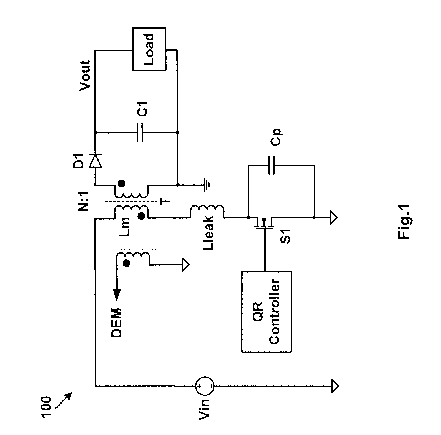
The conventional techniques of flyback PWM systems with QR control may be costly and large in size.

Method used


Image

  • Quasi-resonant systems and methods with multi-mode control
  • Quasi-resonant systems and methods with multi-mode control
  • Quasi-resonant systems and methods with multi-mode control

Examples


Embodiment Construction

[0035]The present invention is directed to quasi-resonant (QR) systems. More particularly, the invention provides dual-mode QR systems and methods that are used for electronic devices. Merely by way of example, the invention has been applied to controllers of switch-mode power converters, such as flyback switch-mode power converters. But it would be recognized that the invention has a much broader range of applicability. For example, the present invention can be applied to devices other than integrated circuits. In another example, the present invention is applicable to any power conversion systems that use QR control.

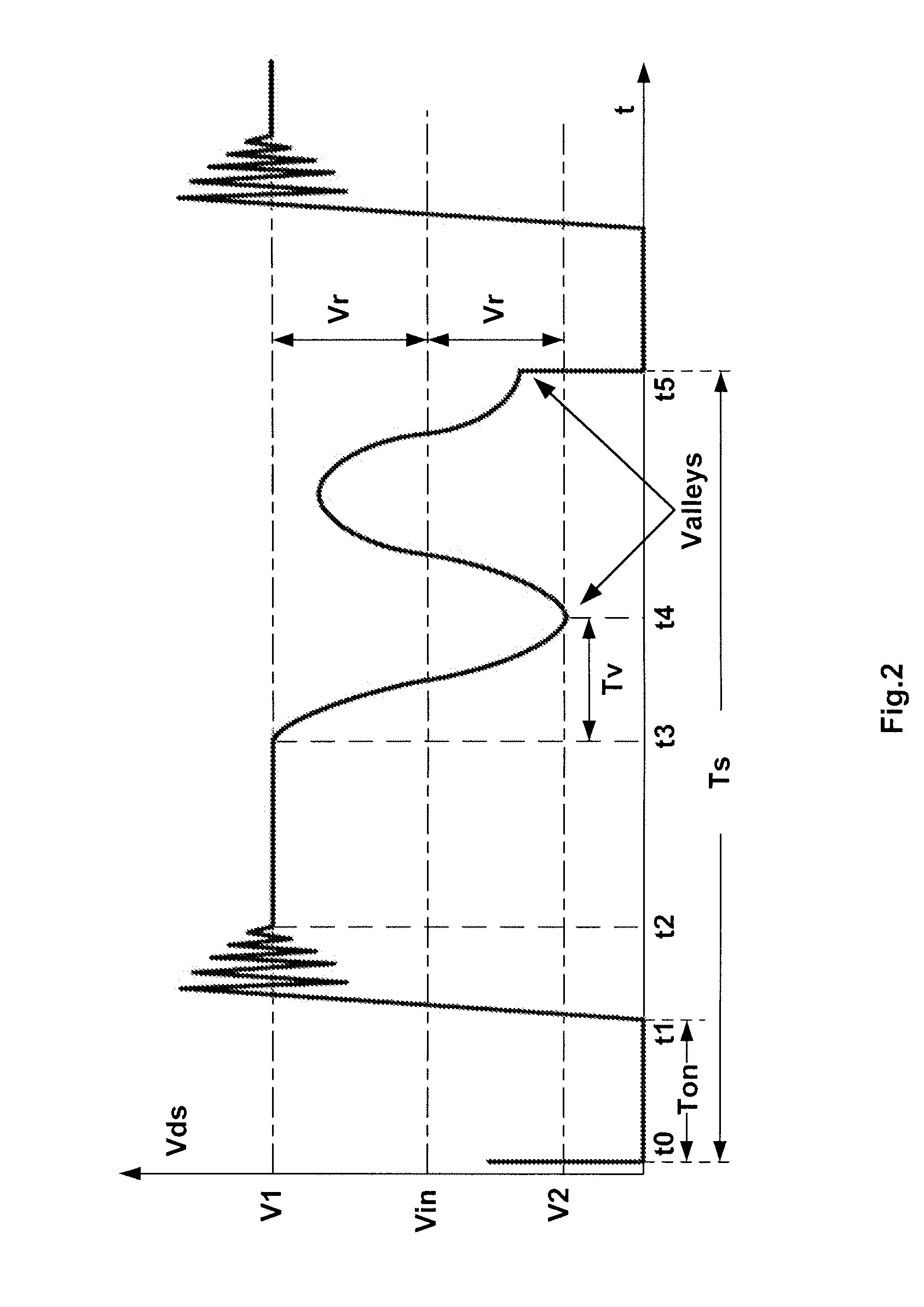
[0036]The conventional techniques have significant drawbacks. For example, if the first valley at t4 is selected to start the new PWM cycle and if Tv is very small in comparison with Ts, the conventional flyback PWM system with QR control may operate under a transition mode, i.e., the CCM / DCM boundary mode, as shown in FIG. 2. Specifically, Tv is a time period from t0 ...


PUM


Abstract

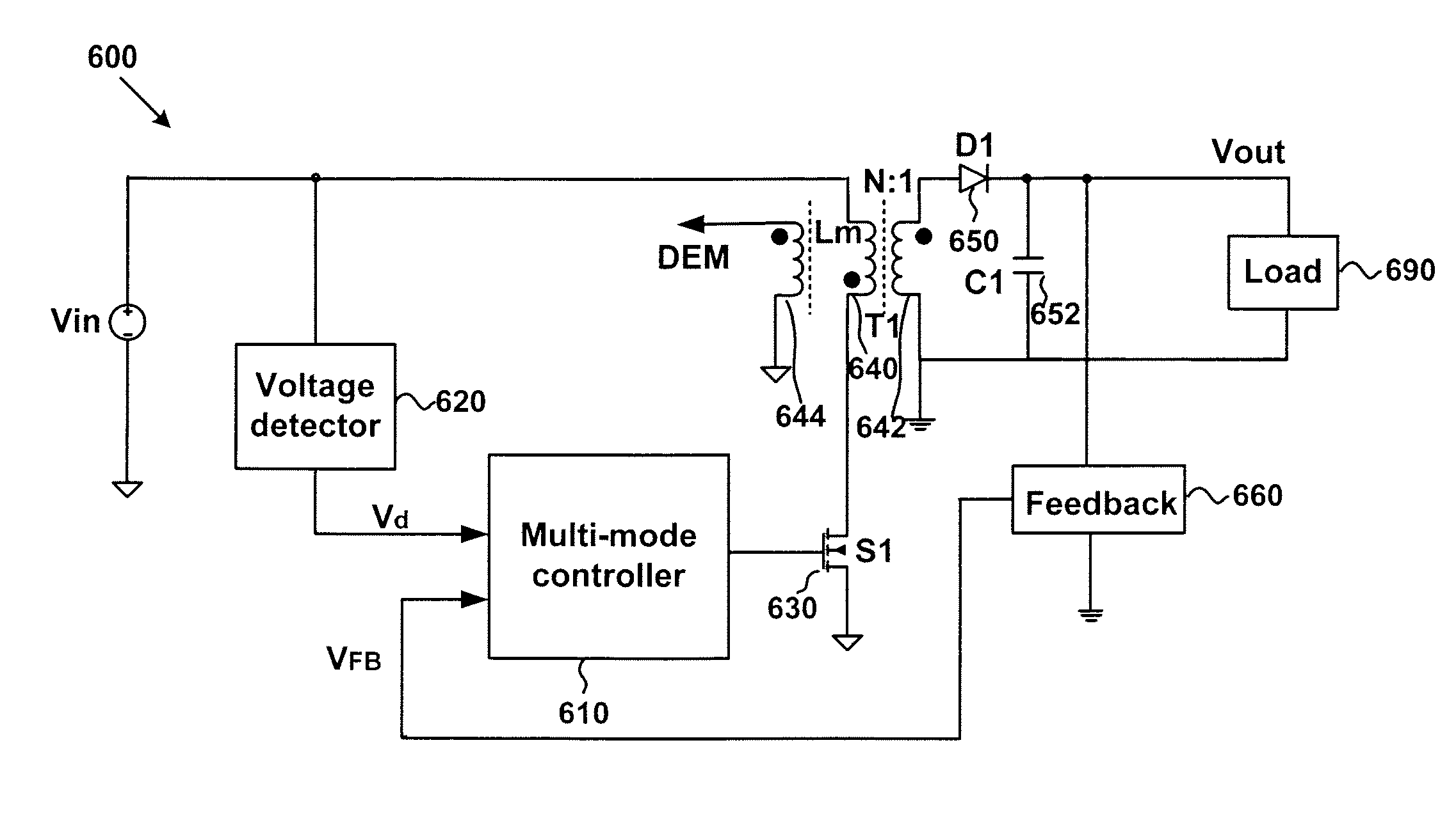
Switch-mode power conversion system and method thereof. The switch-mode power conversion system includes a primary winding configured to receive an input voltage, and a secondary winding coupled to the primary winding and configured to, with one or more other components, generate an output signal. Additionally, the switch-mode power conversion system includes a feedback component configured to receive the output signal and generate a feedback signal based on at least information associated with the output signal, and a voltage detector configured to receive the input voltage and output a detection signal. Moreover, the switch-mode power conversion system includes a mode controller configured to receive the detection signal and the feedback signal and generate a switch signal based on at least information associated with the detection signal and the feedback signal, and a switch configured to receive the switch signal and affect a first current flowing through the primary winding.

Description

1. CROSS-REFERENCES TO RELATED APPLICATIONS[0001]This application claims priority to Chinese Patent Application No. 200910047112.1, filed Mar. 2, 2009, commonly assigned, incorporated by reference herein for all purposes.2. BACKGROUND OF THE INVENTION[0002]The present invention is directed to quasi-resonant (QR) systems. More particularly, the invention provides dual-mode QR systems and methods that are used for electronic devices. Merely by way of example, the invention has been applied to controllers of switch-mode power converters, such as flyback switch-mode power converters. But it would be recognized that the invention has a much broader range of applicability. For example, the present invention can be applied to devices other than integrated circuits. In another example, the present invention is applicable to any power conversion systems that use QR control.[0003]The quasi-resonant (QR) technology has been widely used in power converters for medium and high power levels. Thes...

Claims


Application Information

Patent Timeline
IPC IPC(8): G05F1/10
CPCH02M3/33507Y02B70/1433H02M2001/0022H02M1/0022Y02B70/10
Inventor LIN, YUANYE, JUNFANG, LIEYI
Owner ON BRIGHT ELECTRONICS SHANGHAI
Learn More