Planar lighting device and liquid crystal display device using same

a technology of liquid crystal display device and lighting device, which is applied in the direction of lighting and heating apparatus, semiconductor lasers, instruments, etc., can solve the problems of affecting the display quality of the image, and affecting the illumination effect of the backlight lighting device. , to achieve the effect of reducing power consumption, sufficient uniform luminance, and improving light use efficiency

Inactive Publication Date: 2010-09-02
PANASONIC CORP
View PDF5 Cites 68 Cited by
  • Summary
  • Abstract
  • Description
  • Claims
  • Application Information

AI Technical Summary

Benefits of technology

[0048]The planar lighting device according to the present invention has a sufficient uniform luminance when used as the backlight lighting device of the liquid crystal display device. In addition, the liquid crystal display device of the present invention using the planar lighting device of the present invention as the backlight lighting device is capable of displaying an image with a color reproduction range wider than that of a conventional type liquid crystal display device using a conventional type planar lighting device as backlight illumination. Further, in the liquid crystal display device of the present invention, the polarizing plate on the back side of the liquid crystal display panel can be omitted according to the action of the planar lighting device of the present invention. Therefore, the light use efficiency can be improved, and further its power consumption can be reduced.

Problems solved by technology

If there is a variation in luminance, it extremely deteriorates the image displayed thereon even when its color reproduction range gets wider.
However, almost no configuration example that uses a laser light source as a backlight illumination exists.
Therefore, the conventional liquid crystal display device has a problem that 50% or more of natural light for illumination from the LED of the backlight lighting device or the cold cathode fluorescent lamp are lost.
It significantly lowers the efficiency in its use of light.
However, for now, there has been no document released which discloses the liquid crystal display device using the planar lighting device as the backlight lighting device without a polarizing plate on the back side of the liquid crystal display panel to improve the light use efficiency.

Method used


Image

  • Planar lighting device and liquid crystal display device using same
  • Planar lighting device and liquid crystal display device using same
  • Planar lighting device and liquid crystal display device using same

Examples


first embodiment

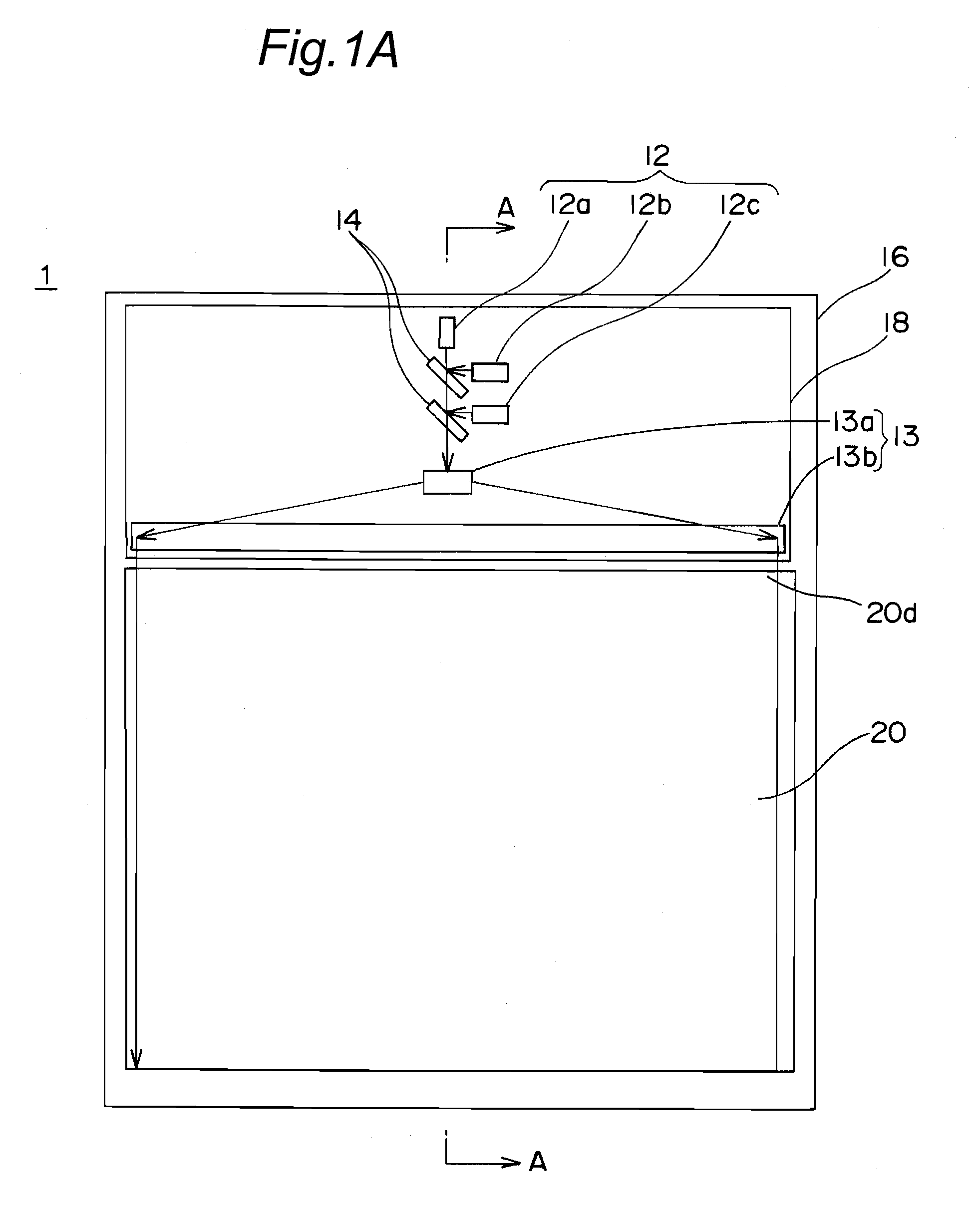
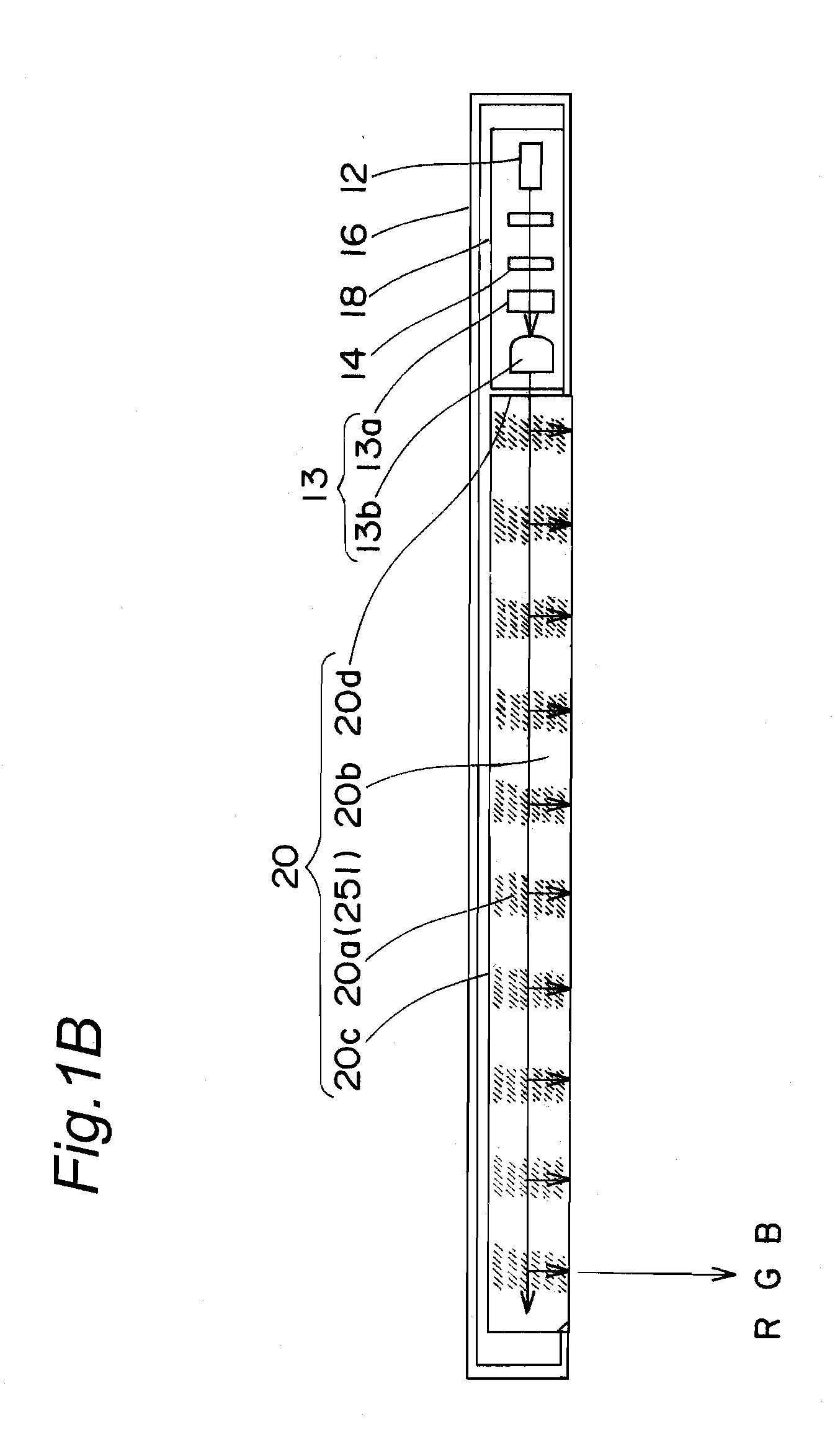
[0107]FIGS. 1A and 1B are diagrams of the planar lighting device according to a first embodiment of the present invention. FIG. 1A is a plan view of an outline of the structure and FIG. 1B is a schematic diagram of a section face along the line A-A of FIG. 1A. Note that in FIG. 1A, surfaces of a casing 16 and a housing part 18 are cutout respectively so that the internal structure be illustrated to be easily understood. In addition, in the present embodiment, as will be described later, an embodiment that uses a hologram layer as an optical element will be described.

[0108]As illustrated in FIG. 1A, the planar lighting device 1 of the first embodiment has a configuration as described below. The planar lighting device 1 has laser light sources 12 (12a, 12b, and 12c), and the laser light sources 12 have at least three light sources for emitting linearly-polarized light of three primary colors such as a red light (R-light) source 12a, a green light (G-light) source 12b, and a blue light...

second embodiment

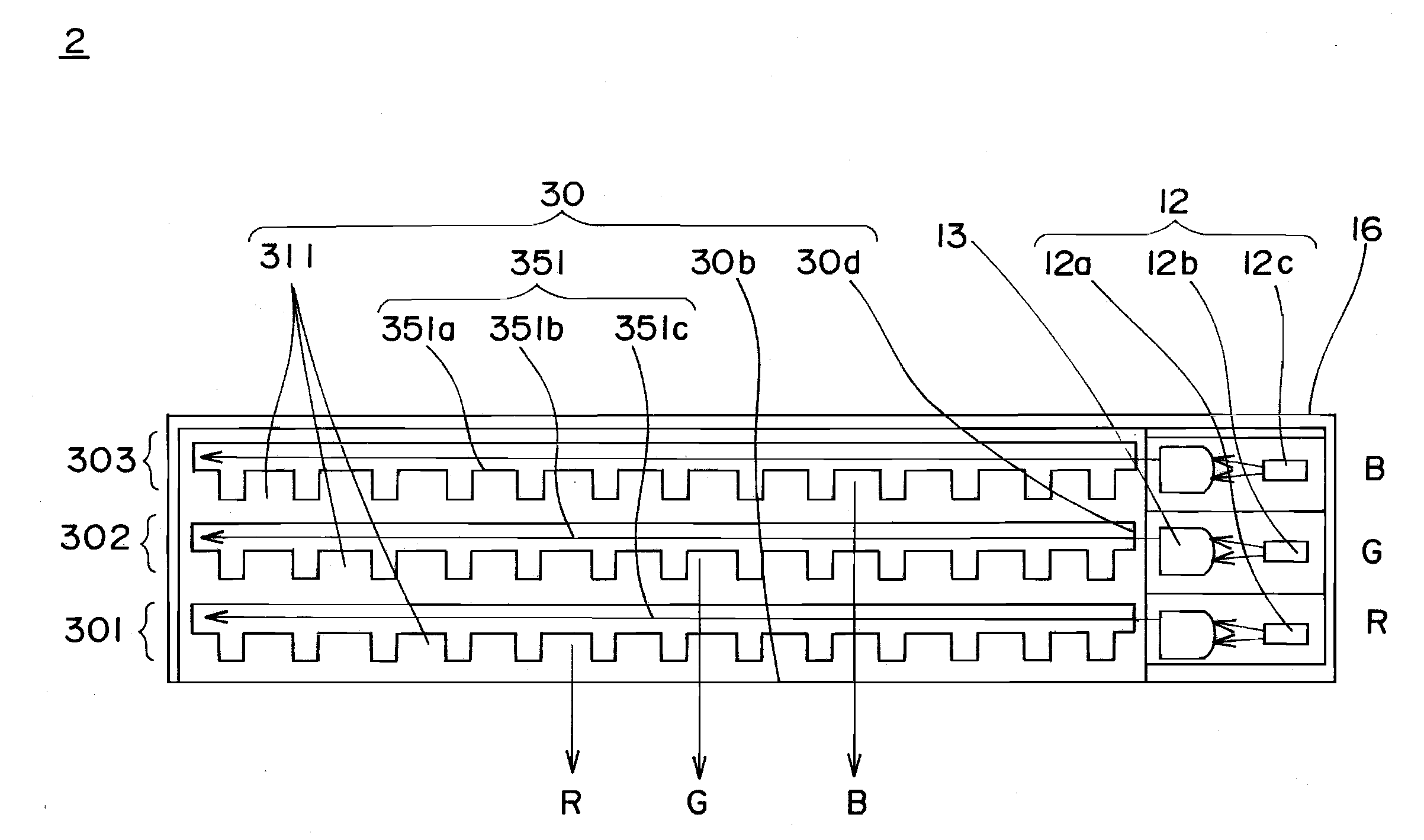
[0143]FIG. 6A and FIG. 6B are views illustrating a planar lighting device 4 according to a second embodiment of the present invention. FIG. 6A is a plan view illustrating an outline of the configuration, and FIG. 6B is a schematic sectional view along the line C-C of FIG. 6A. Even in a case of illustrating this planar lighting device 4, the surfaces of a casing 16 and a housing part 18 are respectively cutout, thus making it easy to understand the internal configuration. The planar lighting device 4 of the present embodiment is different from the planar lighting device 1 of the first embodiment in the point that optical elements 40a of a first light guide plate 40 are semi-transmissive mirrors 451. The semi-transmissive mirrors 451 are arranged at intervals of a specific pitch along the propagation direction of the laser beam propagating through the first light guide plate 40, and at least a part of the laser beam is reflected by the semi-transmissive mirror, which is then propagate...

third embodiment

[0163]FIG. 10A and FIG. 10B are views illustrating a planar lighting device 50 according to a third embodiment of the present invention. FIG. 10A is a plan view illustrating the outline of the structure, and FIG. 10B is a schematic sectional view along the line E-E of FIG. 10A. In this illustration of the planar lighting device 50, the surface of a casing 16 and a housing part 18 are respectively cut-out, thus making it easy to understand the internal structure.

[0164]Explanation will be given hereunder for a different point between the planar lighting device 50 illustrated in FIG. 10A and FIG. 10B, and the planar lighting device of the first embodiment. First of all, the planar lighting device 50 is different from the planar lighting device 1 in the point that an optical path conversion unit 56 is provided, for converting an optical path of the laser beam emitted from the laser light source 12. The optical path conversion unit 56 of the planar lighting device 50 has a function of co...


PUM

PropertyMeasurementUnit
thicknessaaaaaaaaaa
widthaaaaaaaaaa
intersection angleaaaaaaaaaa

Abstract

The present invention provides a planar lighting device (1) including: a laser light source (12) which emits a linearly-polarized laser beam; an optical member (13) which receives the laser beam, then parallelize the laser beam, and emits the parallelized laser beam; and a first plate-shaped light guide (20) which receives the parallelized laser beam from an end face portion (20d) and emits the parallelized laser beam from a first major surface (20b). The first light guide includes an optical element (20a) which receives the linearly-polarized parallelized laser beam propagated through the first light guide and emits at least a part of the linearly-polarized parallelized laser beam in a direction substantially vertical to the first major surface. The present invention also provides a liquid crystal display device (3) using the planar lighting device (1) as a backlight lighting device.

Description

TECHNICAL FIELD[0001]The present invention relates to a planar lighting device using a laser beam as a light source, and a liquid crystal display device using the planar lighting device.BACKGROUND ART[0002]Conventionally, a planar lighting device using a cold cathode fluorescent tube as a light source is widely used as a backlight illumination in a liquid crystal display device using a liquid crystal display panel. The cold cathode fluorescent tube used therein utilizes light emission of a phosphor (fluorescent material), and has a restriction in a displayable color reproduction range. Therefore, various examinations have been carried out for reproducing a further clear and natural tone. Above all, the planar lighting device for backlight using a light emitting diode (an LED element) of three colors such as red light (R-light), green light (G-light), and blue light (B-light) is focused. The light source using the three colors of R-light, G-light, and B-light or a multi-color LED ele...

Claims


Application Information

Patent Timeline
Patent Type & Authority Applications(United States)
IPC IPC(8): G02F1/1335F21V7/04G02B5/32
CPCG02B6/0026G02B6/0028G02B6/003G02B6/0035G02B6/0056G02F2001/133622G02B6/0076G02F1/133603G02F1/133605G02F1/133615G02B6/0066G02F1/133622
Inventor MIZUSHIMA, TETSUROKASAZUMI, KENICHIITOH, TATSUOYAMAMOTO, KAZUHISAKADOWAKI, SHINICHI
Owner PANASONIC CORP
Why Eureka
Try Eureka