Helicopter vibration control system and rotating assembly rotary forces generators for canceling vibrations

a technology of vibration control system and generator, which is applied in the direction of rotors, machines/engines, textiles and paper, etc., can solve the problems of aircraft equipment and occupants being fatigued and worn, damage to the actual structure and components of the vehicle,

Active Publication Date: 2010-09-02
LORD CORP
View PDF61 Cites 21 Cited by
  • Summary
  • Abstract
  • Description
  • Claims
  • Application Information

AI Technical Summary

Benefits of technology

[0012]In an embodiment the invention includes an electronic vibration control system, the system controlling a rotation of a first rotor and a rotation of a second rotor. The system monitors a plurality of sensor signals. The system controls the rotation speed, rotation direction and phase of the first rotor and the rotation speed, rotation direction and phase of the second rotor to minimize a first monitored vibration frequency sensor signal. The system controls a rotation of a third rotor and a rotation of a fourth rotor, with the system controlling the rotation speed, rotation direction and phase of the third rotor and the rotation speed, rotation direction and phase of the fourth rotor to minimize a second monitored vibration frequency sensor signal.

Problems solved by technology

Helicopter vibrations are particularly troublesome in that they can cause fatigue and wear on the equipment and occupants in the aircraft.
In rotating assembly aircraft vehicles such as helicopters, vibrations are particularly problematic in that they can damage the actual structure and components that make up the vehicle in addition to the contents of the vehicle.

Method used


Image

  • Helicopter vibration control system and rotating assembly rotary forces generators for canceling vibrations
  • Helicopter vibration control system and rotating assembly rotary forces generators for canceling vibrations
  • Helicopter vibration control system and rotating assembly rotary forces generators for canceling vibrations

Examples


Embodiment Construction

[0028]Additional features and advantages of the invention will be set forth in the detailed description which follows, and in part will be readily apparent to those skilled in the art from that description or recognized by practicing the invention as described herein, including the detailed description which follows, the claims, as well as the appended drawings.

[0029]Reference will now be made in detail to the present preferred embodiments of the invention, examples of which are illustrated in the accompanying drawings.

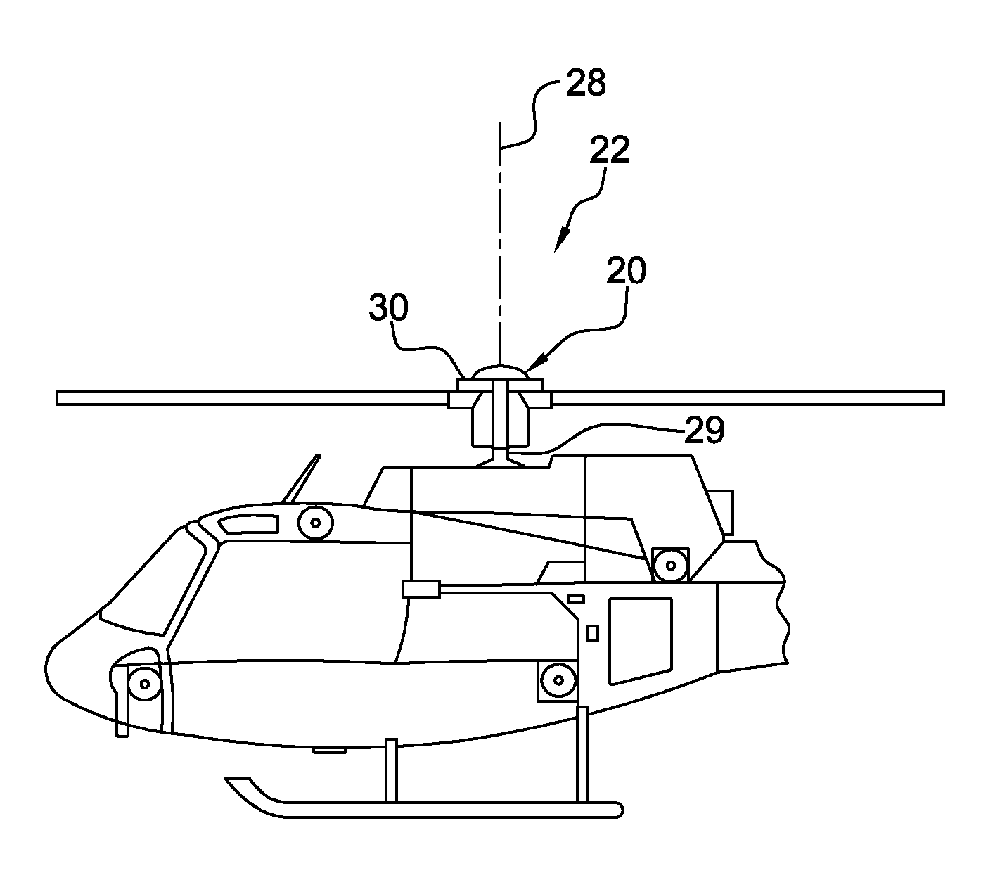
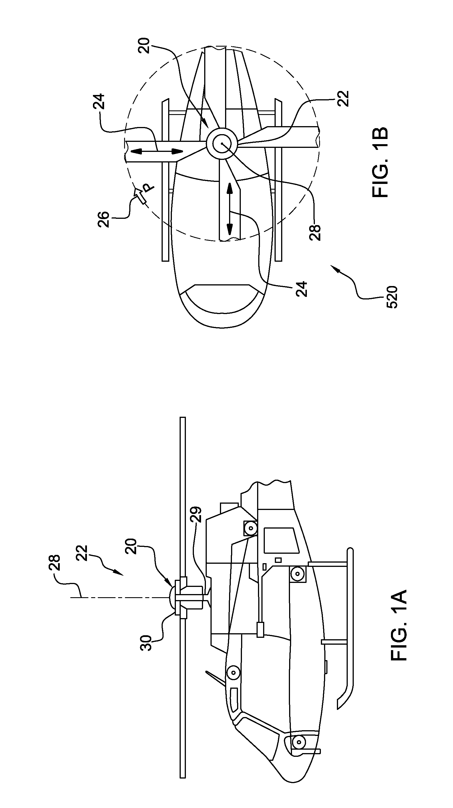
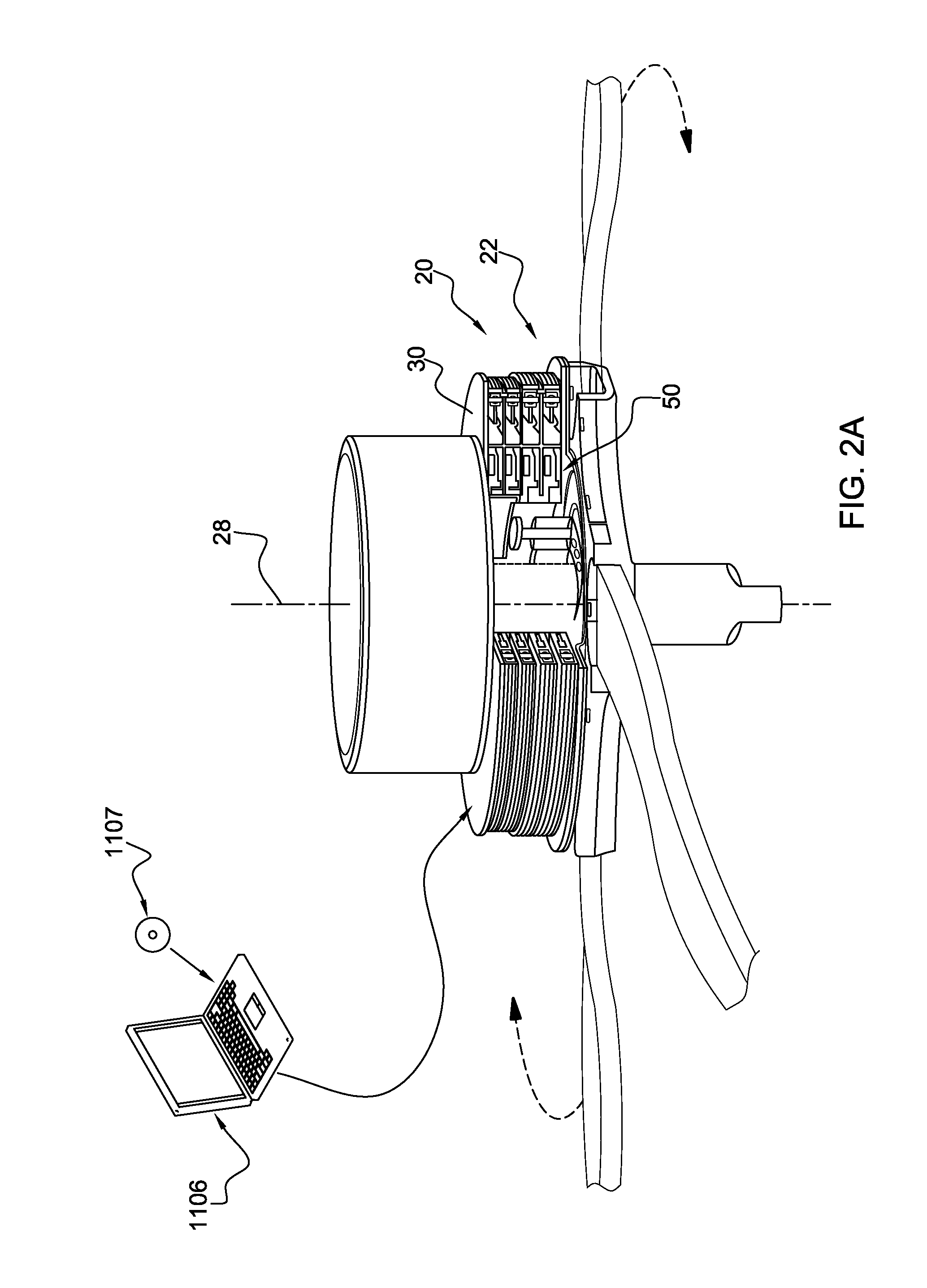
[0030]In an embodiment the invention includes a rotary blade rotary wing aircraft rotating hub mounted rotating assembly vibration control system for a rotary blade rotary wing aircraft rotating hub assembly experiencing a vibration of a plurality of vibration frequencies while rotating at an operational rotation frequency about a rotating assembly center axis of rotation. FIG. 1A-B illustrate a rotary blade rotary wing aircraft rotating hub mounted rotating assembly ...


PUM


Abstract

A rotary blade rotating hub mounted rotating assembly vibration control system including a first imbalance mass concentration rotor, a second imbalance mass concentration rotor, a third imbalance mass concentration rotor, and a fourth imbalance mass concentration rotor. The first imbalance mass concentration rotor has a first imbalance mass concentration rotor center axis rotation centered on the rotating assembly center rotation axis. The second imbalance mass concentration rotor has a second imbalance mass concentration rotor center axis rotation centered on the rotating assembly center rotation axis. The third imbalance mass concentration rotor has a third imbalance mass concentration rotor center axis rotation centered on the rotating assembly center rotation axis. The fourth imbalance mass concentration rotor has a fourth imbalance mass concentration rotor center axis rotation centered on the rotating assembly center rotation axis. The first and second imbalance mass concentration rotors are driven at a first rotation speed greater than the rotating assembly operational rotation frequency while controlling the rotational position of the first imbalance mass concentration and the second imbalance mass concentration to produce a first rotating net force vector to inhibit a first vibration frequency. The third and fourth imbalance mass concentration rotors are driven at a second rotation speed greater than the rotating assembly operational rotation frequency while controlling the rotational position of the third imbalance mass concentration and the fourth imbalance mass concentration to produce a second rotating net force vector to inhibit a second vibration frequency.

Description

CROSS-REFERENCE[0001]This application is a Continuation-In-Part (CIP) of pending U.S. patent application Ser. No. 12 / 286,461 filed on Sep. 30, 2008, which is a Continuation of U.S. patent application Ser. No. 11 / 215,388 filed on Aug. 30, 2005 and now U.S. Pat. No. 7,448,854 issued on Nov. 11, 2008, which claims benefit to U.S. Provisional Application 60 / 605,470 filed on Aug. 30, 2004, all of which the benefit is hereby claimed and are incorporated herein by reference. This application is a Continuation-In-Part (CIP) of pending U.S. patent application Ser. No. 11 / 557,384 filed on Nov. 7, 2006, which claims the benefit of U.S. Provisional Application 60 / 734,232 filed on Nov. 7, 2005 and is also a Continuation of U.S. patent application Ser. No. 11 / 215,388 filed on Aug. 30, 2005 and now U.S. Pat. No. 7,448,854 issued on Nov. 11, 2008, which claims benefit to U.S. Provisional Application 60 / 605,470 filed on Aug. 30, 2004, all of which the benefit is hereby claimed and are incorporated h...

Claims


Application Information

Patent Timeline
Patent Type & Authority Applications(United States)
IPC IPC(8): B64C27/51
CPCB64C27/001B64C2027/003F16F15/223F04D29/662F04D27/02
Inventor JOLLY, MARK R.MEYERS, ANDREW D.
Owner LORD CORP
Why Eureka
Try Eureka