Flared tip turbine blade

a turbine blade and blade technology, applied in the field of turbine blades, can solve the problems of remarkably complex aerodynamic design of turbine airfoils, correspondingly complex flow streams, and combustion gases which leak over the airfoils in the required tip clearance, and achieve little, if any, useful work

Active Publication Date: 2010-09-02
GENERAL ELECTRIC CO
View PDF31 Cites 32 Cited by
  • Summary
  • Abstract
  • Description
  • Claims
  • Application Information

AI Technical Summary

Problems solved by technology

However, aerodynamic design of turbine airfoils is remarkably complex in view of the three dimensional (3D) configurations of the individual airfoils in complete rows thereof, and the correspondingly complex flow streams of the combustion gases channeled between the airfoils during operation.
However, the combustion gases which leak over the airfoil tips in the required tip clearance perform little, if any, useful work.
Th

Method used


Image

  • Flared tip turbine blade
  • Flared tip turbine blade
  • Flared tip turbine blade

Examples


Embodiment Construction

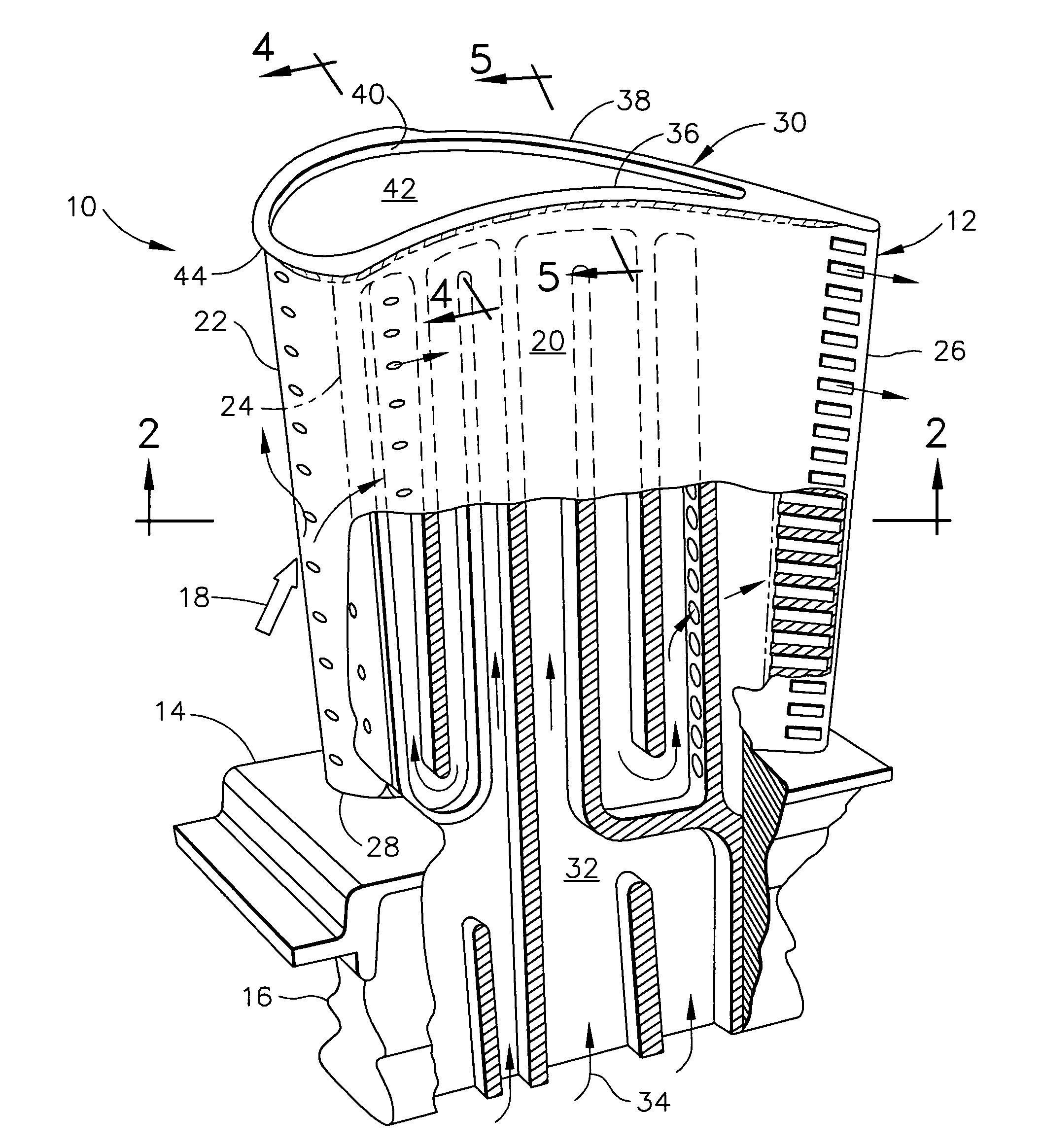
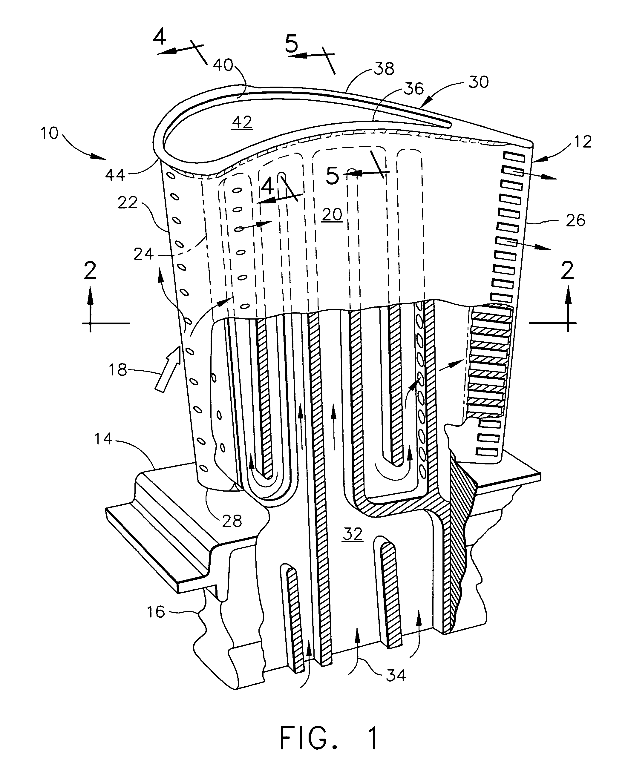
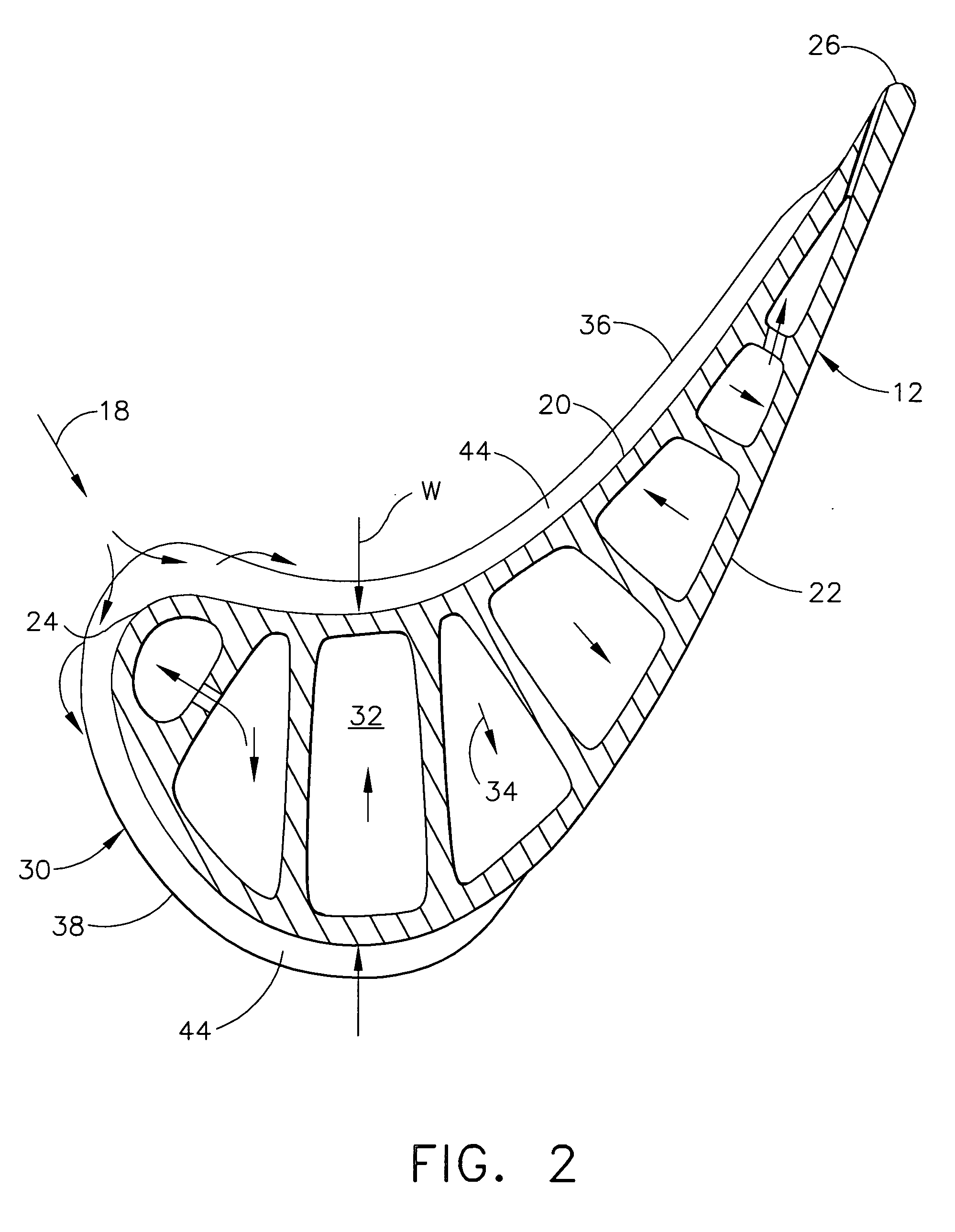
[0025]FIG. 1 illustrates an exemplary first stage turbine rotor blade 10 for use in the HPT of a gas turbine engine. The blade is typically cast from superalloy metal with an airfoil 12, platform 14 at the root thereof, and a supporting dovetail 16 in an integral, one-piece assembly.

[0026]The dovetail 16 may have any conventional form, such as the axial-entry dovetail illustrated in FIG. 1, which mounts the blade in a corresponding dovetail slot in the perimeter of a supporting rotor disk (not shown). The disk holds a full row of the blades spaced circumferentially apart from each other to define inter-blade flow passages therebetween.

[0027]During operation, combustion gases 18 are generated in the combustor of the engine (not shown) and suitably channeled downstream over the corresponding turbine blades 10 which extract energy therefrom for powering the supporting rotor disk. The individual platform 14 provides a radially inner boundary for the combustion gases and adjoins adjacent...


PUM


Abstract

A turbine blade includes an airfoil terminating in a tip. The tip includes a first rib conforming with a concave pressure side of the airfoil, and a second rib conforming with a convex suction side of the airfoil. The second rib is flared outwardly from the suction side.

Description

BACKGROUND OF THE INVENTION[0001]The present invention relates generally to gas turbine engines, and, more specifically, to turbine blades therein.[0002]In a gas turbine engine, air is pressurized in a compressor and mixed with fuel for generating combustion gases in a combustor. Various turbine stages extract energy from the combustion gases to power the engine and produce work.[0003]A high pressure turbine (HPT) immediately follows the combustor and extracts energy from the hottest combustion gases to power the upstream compressor through one drive shaft. A low pressure turbine (LPT) follows the HPT and extracts additional energy from the combustion gases for powering another drive shaft. The LPT powers an upstream fan in a turbofan aircraft engine application, or powers an external shaft for marine and industrial applications.[0004]Engine efficiency and specific fuel consumption (SFC) are paramount design objectives in modern gas turbine engines. The various turbine rotor blades ...

Claims


Application Information

Patent Timeline
IPC IPC(8): F01D5/18B64C27/46
CPCF01D5/20Y02T50/673F05D2250/712Y02T50/60
Inventor KLASING, KEVIN SAMUELLEE, CHING-PANGVITT, PAUL HADLEYKEITH, BRIAN DAVID
Owner GENERAL ELECTRIC CO
Why Eureka
Try Eureka