Supercharge Your Innovation With Domain-Expert AI Agents!

Turbine blade cooling

a turbine blade and cooling technology, applied in the direction of machines/engines, liquid fuel engines, mechanical equipment, etc., can solve the problems of engine size, rotational speed, additional strain on parts,

Active Publication Date: 2010-09-02
GENERAL ELECTRIC CO
View PDF10 Cites 29 Cited by
  • Summary
  • Abstract
  • Description
  • Claims
  • Application Information

AI Technical Summary

Benefits of technology

The patent describes a turbine blade with a hollow airfoil that has a chamber for receiving a coolant. The blade has inserts that direct the coolant towards the inner surface of the outer wall. These inserts also create channels for the coolant to flow through. The technical effect of this design is improved cooling of the turbine blade, which helps to increase its efficiency and durability.

Problems solved by technology

While several strategies for increasing the efficiency of turbine engines are known, it remains a challenging goal because the known alternatives, which, for example, include increasing the size of the engine, increasing the temperatures through the hot-gas path, and increasing the rotational velocities of the rotor blades, generally place additional strain on parts, including additional strain on turbine airfoils, which are already highly stressed.
This type of cooling, which is commonly referred to as “film cooling,” however, comes at an expense.
The release of the compressed air in this manner over the surface of the airfoil, lowers the aero-efficiency of the engine.

Method used


Image

  • Turbine blade cooling
  • Turbine blade cooling
  • Turbine blade cooling

Examples


Embodiment Construction

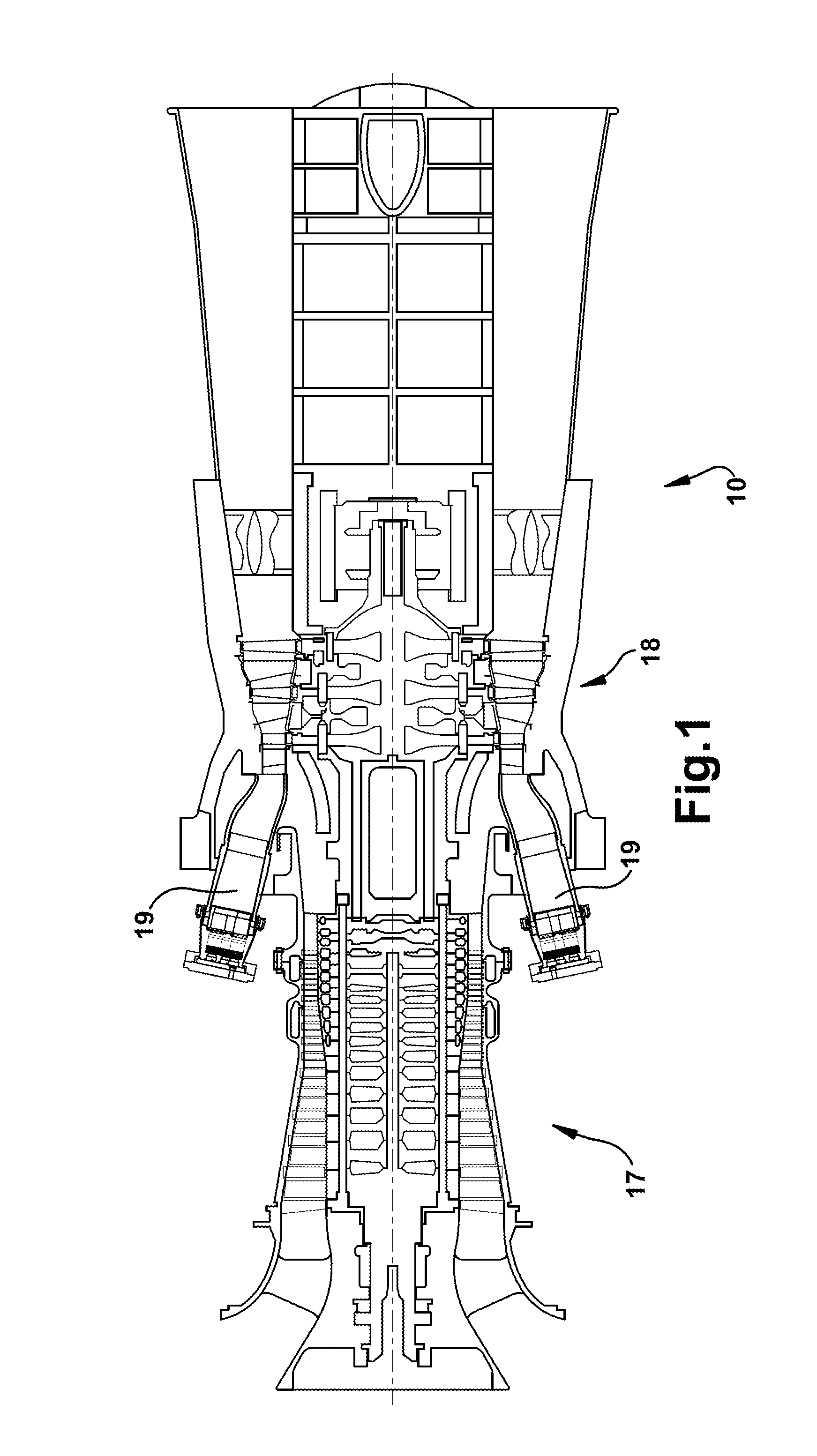
[0017]Referring now to the figures,FIG. 1 illustrates a schematic representation of a gas turbine engine 10. In general, gas turbine engines operate by extracting energy from a pressurized flow of hot gas that is produced by the combustion of a fuel in a stream of compressed air. As illustrated in FIG. 1, gas turbine engine 10 may be configured with an axial compressor 17 (though other types of compressors are possible) that is mechanically coupled by a common shaft or rotor to a downstream turbine section or turbine 18, and a combustor 19 positioned between the compressor 19 and the turbine 18. Note that the following invention may be used in all types of turbine engines, including gas turbine engines, steam turbine engines, aircraft engines, and others. Hereinafter, the invention will be described in relation to a gas turbine engine. This description is exemplary only and not intended to be limiting in any way.

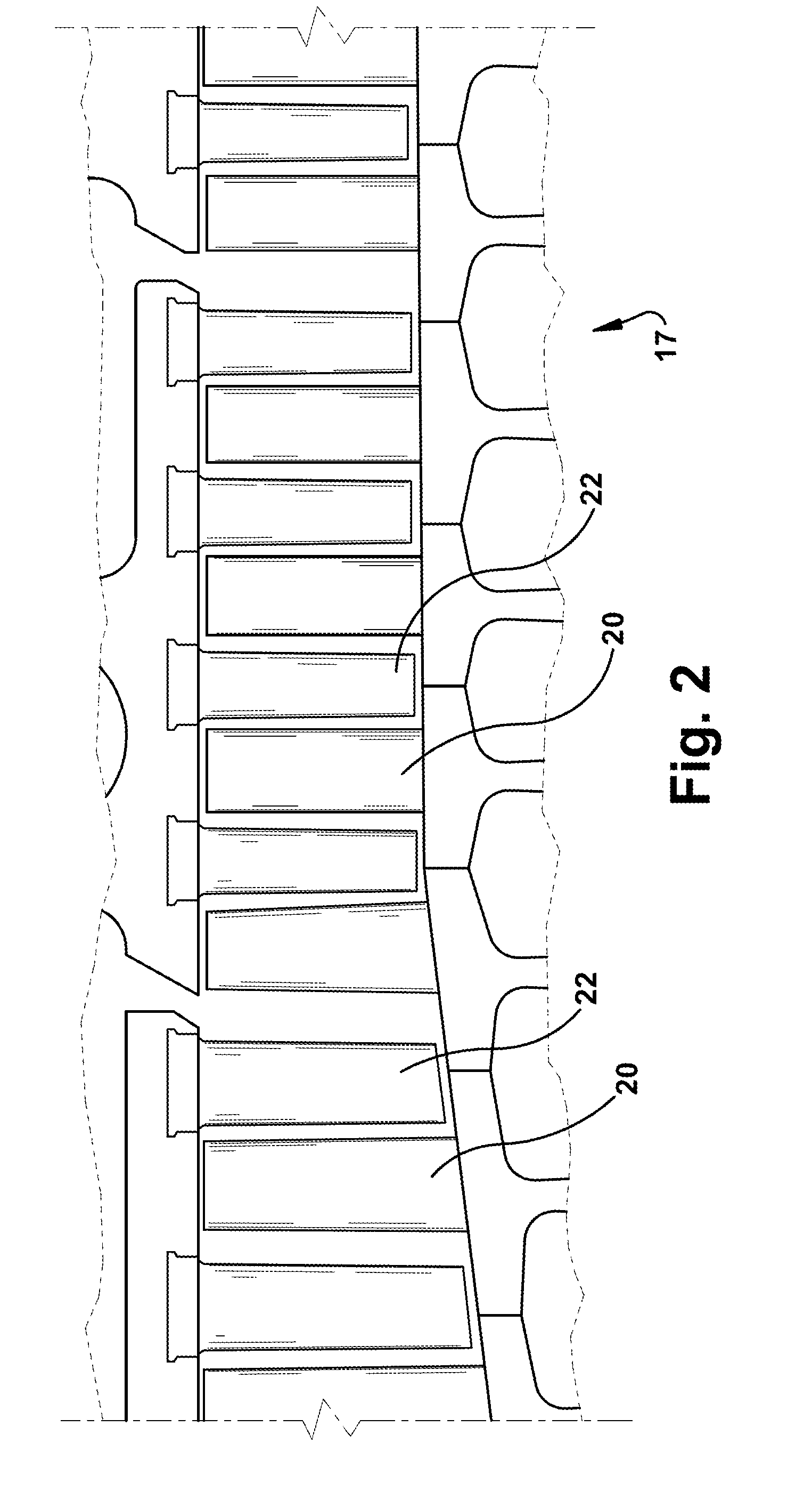
[0018]FIG. 2 illustrates a view of an exemplary multi-staged axial comp...


PUM


Abstract

A turbine blade with a generally hollow airfoil having an outer wall that defines at least one radially extending chamber for receiving the flow of a coolant, the airfoil including a leading edge that resides in an upstream or forward direction, a trailing edge that resides in a downstream or aft direction, a convex suction side, and a concave pressure side, the turbine blade comprising: a plurality of inserts disposed within the chamber that are configured to initially receive at least a portion of the coolant entering the chamber and direct a substantial portion of the coolant through a plurality of insert apertures toward the inner surface of the outer wall; wherein the inserts are configured to form at least one inward bleed channel and a central collector passage into which the inward bleed channel flows.

Description

BACKGROUND OF THE INVENTION[0001]This present application relates generally to apparatus, methods and / or systems for improving the efficiency and / or operation of turbine engines. More specifically, but not by way of limitation, the present application relates to apparatus, methods and / or systems for cooling turbine airfoils via the circulation and impingement of a coolant through internal cooling circuits or passageways.[0002]A gas turbine engine typically includes a compressor, a combustor, and a turbine. (Note that although the present invention is described primarily in reference to an exemplary power generating gas turbine engine, it is not so limited, and this reference is provided only as an example. A person of ordinary skill in the art will appreciate that embodiments of the present invention also may be used in aircraft engines and other types of rotary engines.) The compressor and turbine generally include rows of turbine blades or airfoils that are axially stacked in stag...

Claims


Application Information

Patent Timeline
Patent Type & Authority Applications(United States)
IPC IPC(8): F01D5/18
CPCY02T50/676F01D5/189Y02T50/60
Inventor PAL, DIPANKARTHOMPSON, JAMES E.
Owner GENERAL ELECTRIC CO
Features
  • R&D
  • Intellectual Property
  • Life Sciences
  • Materials
  • Tech Scout
  • Unparalleled Data Quality
  • Higher Quality Content
  • 60% Fewer Hallucinations
Learn More