
Radio network controller and transmission power control method

a radio network controller and transmission power technology, applied in the direction of power management, transmission monitoring, multiplex communication, etc., can solve the problems of deteriorating radio quality, affecting the quality of radio signals, and increasing the control load of the radio network controller, so as to prevent deterioration of radio quality and reduce the control load

Inactive Publication Date: 2010-09-02
NTT DOCOMO INC
View PDF3 Cites 13 Cited by
  • Summary
  • Abstract
  • Description
  • Claims
  • Application Information

AI Technical Summary

Benefits of technology

The present invention provides a radio network controller and a transmission power control method that can prevent a deterioration of radio quality when a link environment is changed, and can reduce a control load on the radio network controller and the bandwidth between the radio network controller and the radio base station. The technical effects of the invention include reducing the impact of changes in the radio environment on signal quality, reducing the load on the network controller and base station, and improving overall network performance.

Problems solved by technology

However, when the target SIR is changed at every TTI (Transport Time Interval), control load on the radio network controller may be increased.
Further, a bandwidth of an interface between the radio network controller and the radio base station may be largely consumed.
However, when the target SIR calculated based on this method is adopted, the quality is kept deteriorated for the above-described time section, due to the difference between the target quality and the set target SIR.
There has been a problem that the communication quality for this time section can be largely deteriorated at this time, since the target SIR is kept unchanged.

Method used


Image

  • Radio network controller and transmission power control method
  • Radio network controller and transmission power control method
  • Radio network controller and transmission power control method

Examples


Embodiment Construction

[0015]Next, with reference to the accompanying drawings, embodiments of the present invention will be described. In the description of the drawings, the same or similar reference numerals denote the same or similar elements. However, it should be noted that the drawings are schematic.

(Configuration of Communication System)

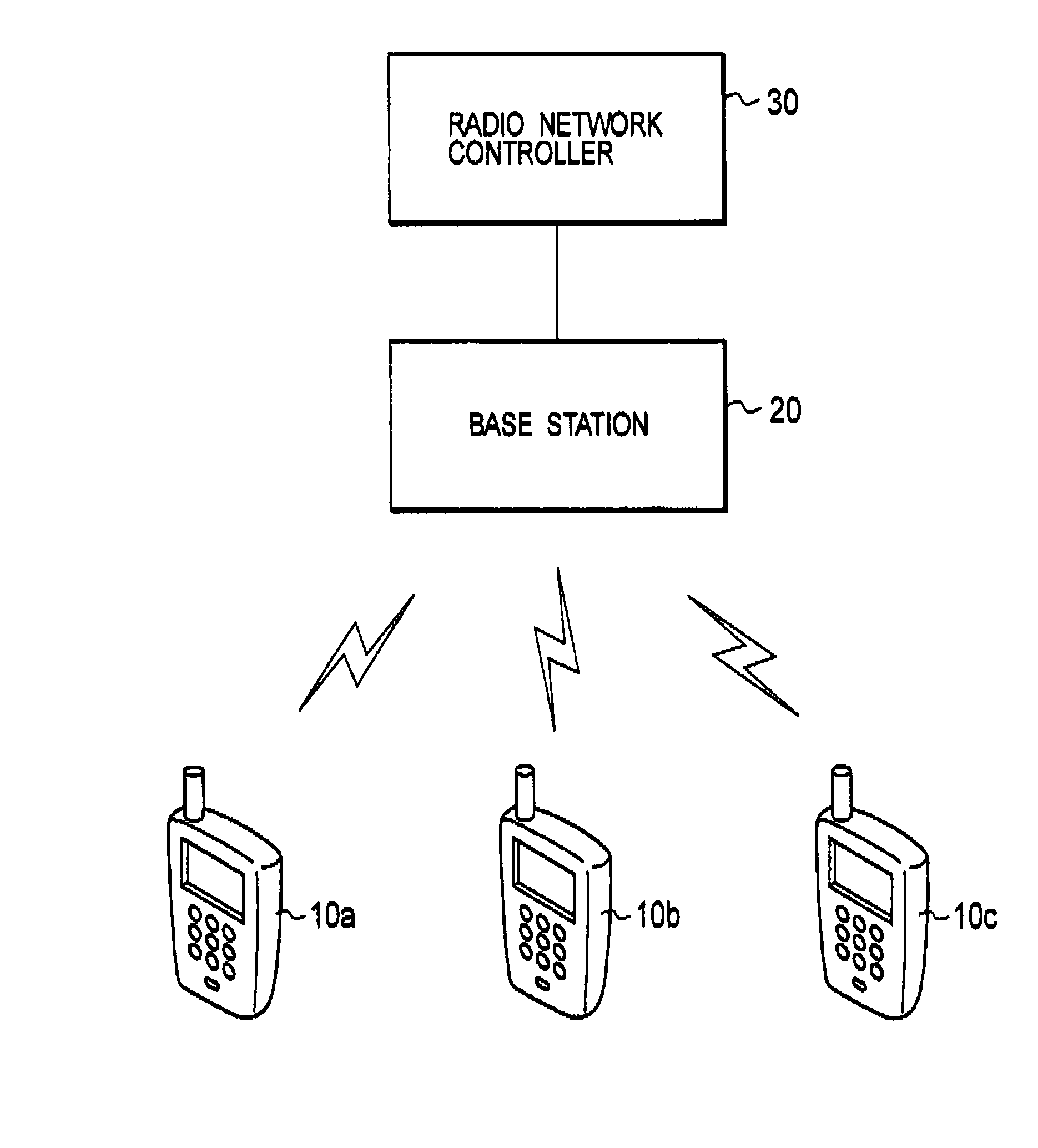
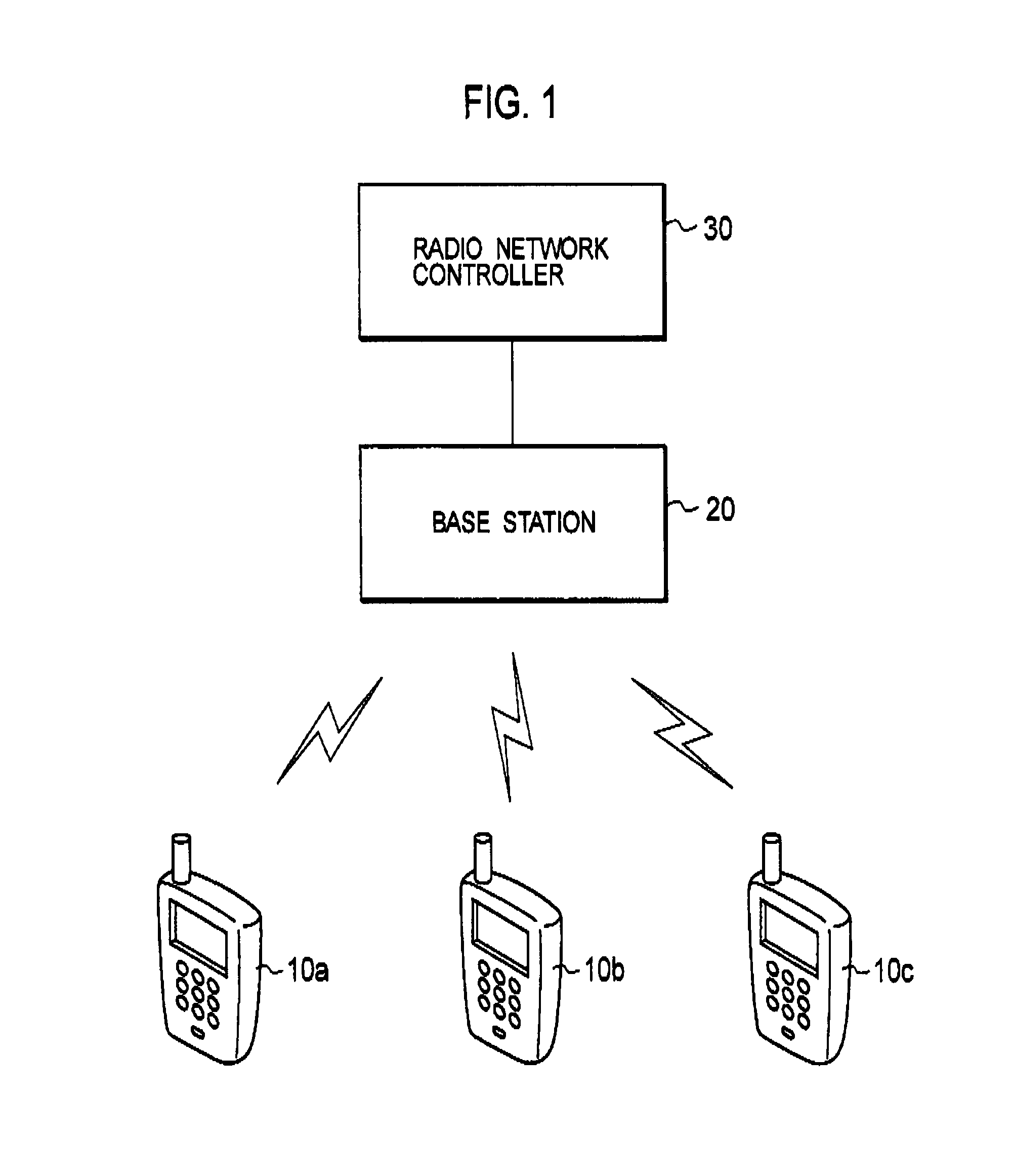
[0016]As shown in FIG. 1, a communication system according to an embodiment includes a base station 20 wirelessly connected to a plurality of mobile stations 10a, 10b, 10c, and a radio network controller 30 controlling the base station 20. Incidentally, although the number of the mobile station performing radio communication with the base station is set to “3” in the present embodiment, the number of the mobile station is not limited to “3”.

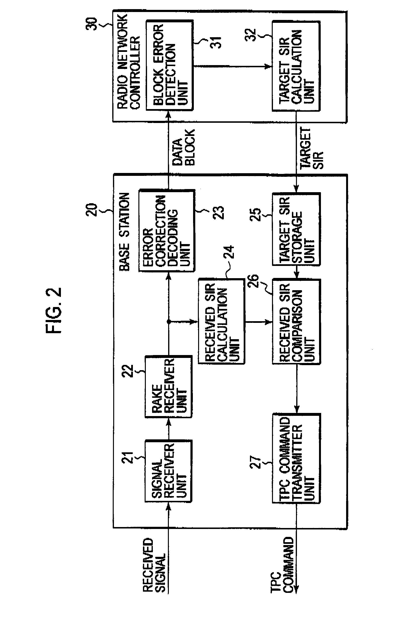
[0017]According to the communication system of the present embodiment, the inner loop transmission power control is adopted between the mobile stations 10a, 10b, 10c, and the base station 20. Further, the outer loop transmission...


PUM


Abstract

The radio network controller 30 includes a block error detection unit 31 configured to receive a data block from the base station 20 and to detect a block error, and a target SIR calculation unit 32 configured to calculate a target SIR based on the detected block error rate.The target calculation unit 32 sets the first time section, which indicates a time section from a detection of the block error to the notification of the target SIR is to the base station 20 when the block error is detected, shorter than a second time section, which indicates a time section from the detection of the block error to the notification of the target SIR to the base station 20 when the block error is not detected.

Description

TECHNICAL FIELD[0001]The present invention relates to a radio network controller and a transmission power control method.BACKGROUND ART[0002]A CDMA mobile communication system makes it possible to maintain a communication quality at a desired level and to minimize an interference causing to the other users, by performing a transmission power control with a high accuracy. Accordingly, the COMA mobile communication system can increase a radio system capacity. The CDMA mobile communication system includes two steps of a configuration in order to maintain a received SIR (Signal to Interference power Ratio) closer to a target SIR: an inner loop transmission power control and an outer loop transmission power control. In the inner loop transmission power control, a radio base station measures the received SIR and compares the received SIR with the target SIR, and instructs, to a mobile station, to increase or decrease the transmission power by using a transmission power control bit. In the...

Claims


Application Information

Patent Timeline
Patent Type & Authority Applications(United States)
IPC IPC(8): H04B7/00H04B1/7103H04J13/00H04L1/00H04W52/04H04W52/08H04W52/10H04W52/12H04W52/24H04W92/00
CPCH04L1/0026H04L1/0057H04W52/04H04W52/08H04W52/386H04W52/20H04W52/241H04W52/362H04W52/10H04L5/006
Inventor USUDA, MASAFUMIUMESH, ANILANDO, HIDEHIROSATO, TAKUYASASAKI, SHINICHIMAKINO, KOUJI
Owner NTT DOCOMO INC
Learn More