
Control and communication system

a communication system and control technology, applied in the direction of ratio control, flow control, valve details, etc., can solve the problems of consuming energy, consuming energy, and reducing the use of water for irrigation systems in agricultural, commercial, industrial, recreational or residential sites

Inactive Publication Date: 2010-09-02
WATER OPTIMIZER
View PDF22 Cites 67 Cited by
  • Summary
  • Abstract
  • Description
  • Claims
  • Application Information

AI Technical Summary

Benefits of technology

[0034]In a more specific embodiment of the invention, the multiplicity of user wireless transceiver forms a wireless mesh network for communication with a third party wireless transceiver. Examples of the information communicated to a third party wireless transceiver unrelated to liquid flow include information from parking meters, electrical meters, gas meters, street lights, rain fall gauges, soil moisture gages, weather stations, security and smart home systems.
[0035]The invention is also embodied in a remote controlled valve unit for an irrigation system comprising an electrically operated valve powered by a battery. A wireless transceiver for communicates with adjacent wireless transceivers. A control is interconnected to the electrically operated valve and the battery and the wireless transceiver for opening and closing the electrically operated valve in accordance with communications from the remote transceiver. a photovoltaic device is connected to the battery for charging the battery upon impingement of electromagnetic radiation.
[0036]The invention i

Problems solved by technology

These liquid control systems have resulted in a substantial reduction of the use of water for irrigation systems in agricultural, commercial, industrial, recreational or residential sites.
The at least one device controllably consumes energy.
Although the liquid control systems set forth in the foregoing United States Patents have reduced the use of water, these liquid control systems have not addressed the problems associated with the water distribution systems between a water source and an agricultural, commercial, industrial, recreational or residential site.
The recent and substantial increase in the number of agricultural, commercial, industrial, recreational or residential sites have placed an excessive burden upon the existing distribution systems between the water source and the agricultural, commercial, industrial, recreational or residential sites.
Many of these liquid distribution systems have not been upgraded to accommodate for recent and substantial increase in the number of agricultural, commercial, industrial, recreational or residential sites due to the substantial time, substantial inconvenience and the substantial cost of upgrading associated with upgrading these distribution systems.
The above mentioned have contributed to the water management in agricultural, commercial, industrial, recreational or residential sites but have not addressed the issue of the management of water from a water provider to the agricultural, commercial, industrial, recreational or residential sites.
The recent and substantial increase in the number of agricultural, commercial, industrial, recreational or residential site sites have placed an excessive burden upon the existing distribution systems between the water source and the agricultural, commercial, industrial, recreational or residential sites.
Many of these liquid distribution systems have not been upgraded to accommodate for recent and substantial increase in the number of agricultural, commercial, industrial, recreational or residential sites due to the substantial time, substantial inconvenience and the substantial cost of upgrading associated with upgrading these distribution systems.

Method used


Image

  • Control and communication system
  • Control and communication system
  • Control and communication system

Examples


example 1

Root Zone Working Water Storage

[0141]

First Cycle Adjustment=0.55−0.55(0.167×0.10)=0.5408

Second Cycle Adjustment=0.5408−0.5408(−0.133×0.10)=0.5480

example 2

Crop Coefficient (KC)

[0142]

First Cycle Adjustment=0.71−(−0.71)(0.167×0.20)=0.7337

Second Cycle Adjustment=0.7337−(−0.7337)(0.133×0.20)=0.7142

[0143]Table 4 sets forth a second example of initial parameters entered into the adaptive control 400.

TABLE 4UserDefinedSecondOriginalCorrectionFirst CycleCycleDescriptionParametersValueAdjustmentAdjustment1Soil TextureSandy Loam——2Slope %12%—3Exposure50%——4Root Zone Working 2.000.052.01111.9999Water Storage(RZWWS) in5VegetationWoody Shrubs——6Crop CoefficientN / A(June) (KC)7LandscapeCoefficientKs0.50.100.48890.4943KD1.00.100.97780.9887KMC0.80.050.79110.7955KL 0.408Precipitation 1.401.44671.4226Rate (PR)(in / hr)9Estimated75 79.1776.97ApplicationEfficient %10Basic Soil0.4 In / Hr0.41330.4064Intake Rate(in)11Allowable Surface0.240.150.24800.2439Accumulation ASA(in)TOTAL1.0

[0144]Table 5 sets forth an example of user defined parameters entered into the adaptive control 400.

TABLE 5Target Moisture Value9%Tolerance Range5%Acceptable RangeFrom 9.45%To 8.55%

[...

example 3

Root Zone Working Water Storage

[0148]Root Zone Working Water Storage

First Cycle Adjustment=2.00−2.00(−0.2222×0.05)=2.0111

Second Cycle Adjustment=2.0111−2.0111(0.1111×0.05)=1.9999


PUM


Abstract

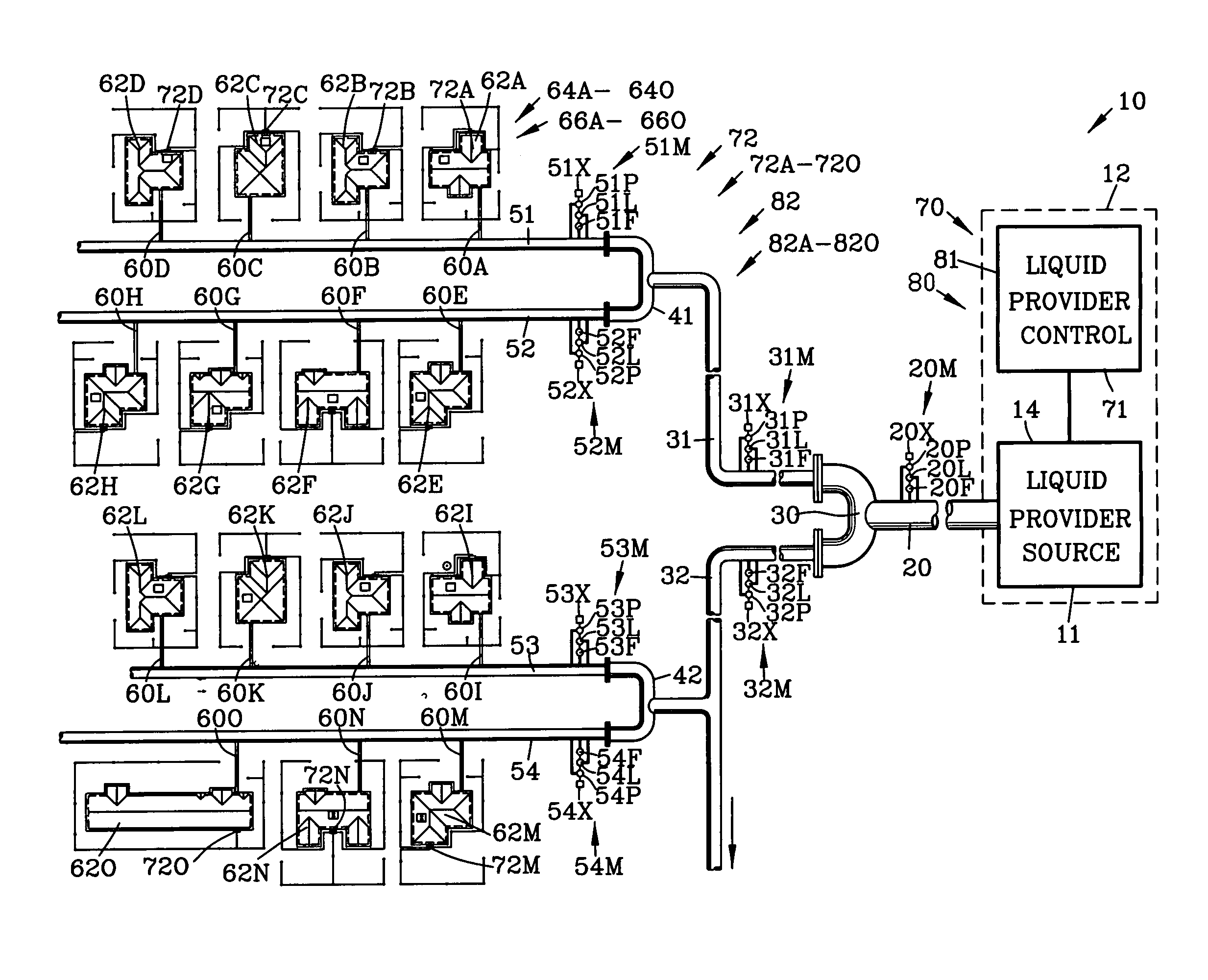
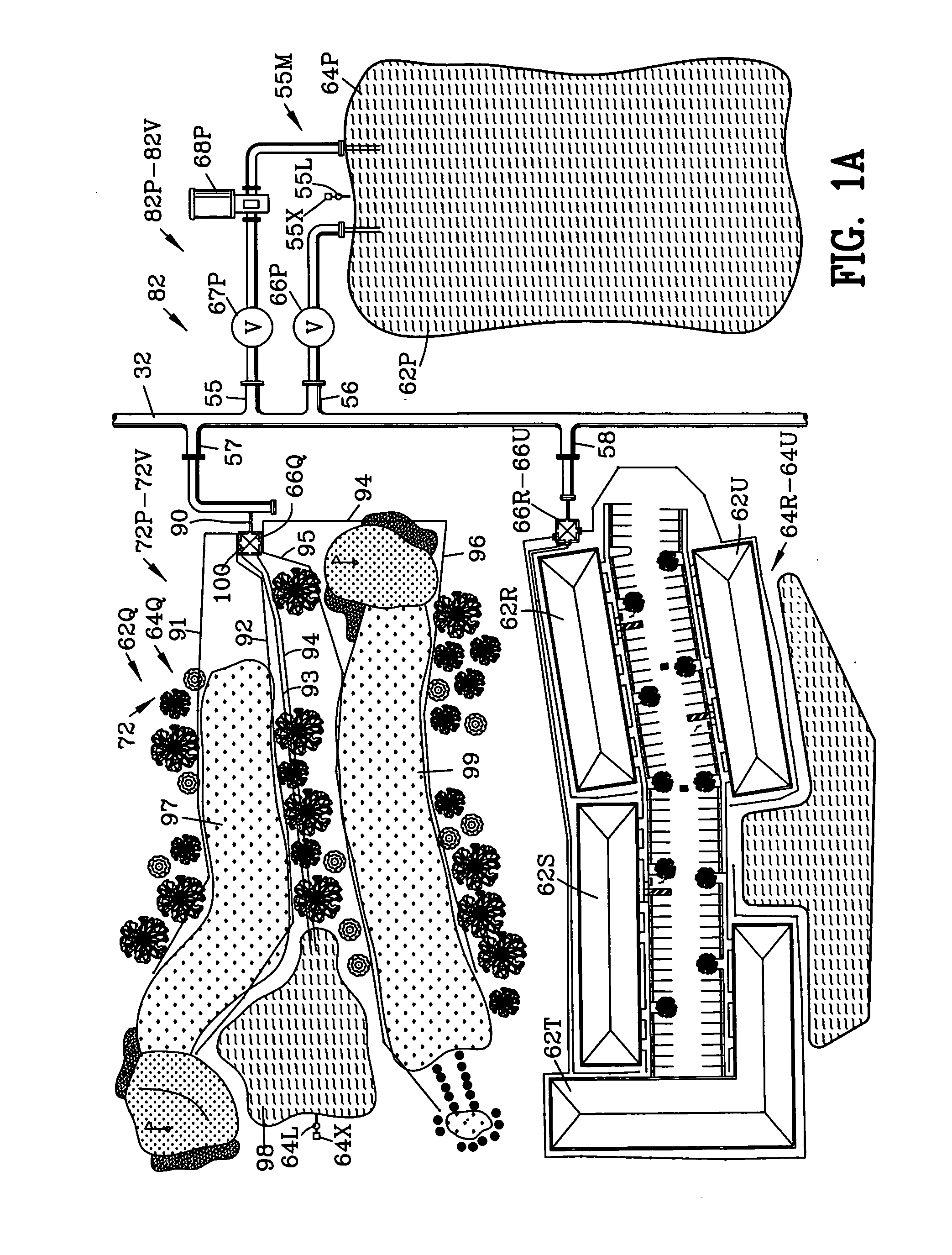
A combined water management and communication system for a water provider wirelessly communicating with selected ones of the multiplicity of user wireless transceiver for changing water distribution to selective ones of the multiplicity of independent users upon an undesired water flow characteristic within the water distribution channels. The multiplicity of user wireless transceivers communicating with proximate user wireless transceivers for forming a network for communicating information to a third party wireless transceiver unrelated to liquid flow. The invention is also incorporated into a remote controlled solar operated wireless irrigation valve. The invention is further incorporated into an improved water management irrigation system incorporating an adaptive weather based controller that is adjusted by a weather based sensor base controller.

Description

BACKGROUND OF THE INVENTION[0001]1. Field Of The Invention[0002]This invention relates to the control of liquid and more particularly to the control of fluids in a fluid distribution system in combination with a wireless communication system.[0003]2. Background of the Invention[0004]The prior art has proposed various types of liquid control systems for controlling the flow and distribution of liquids. Some of these prior art liquid control systems relate to water control systems for controlling the flow and distribution of water. Recently, many water control systems have been provided to manage the volume of water used by agricultural, commercial, industrial, recreational or residential sites. These water management control systems have reduced the volume of water used through the limitation of the volume of water used and / or by reclaiming water. These liquid control systems have resulted in a substantial reduction of the use of water at commercial, industrial, recreational or resid...

Claims


Application Information

Patent Timeline
IPC IPC(8): G05D7/06
CPCA01G25/16G05D7/0664E03B7/02Y10T137/189
Inventor O'CONNOR, THOMAS M.
Owner WATER OPTIMIZER
Learn More