Control apparatus and method for automatic transmission system

a control apparatus and automatic transmission technology, applied in fluid gearings, gearings, instruments, etc., can solve the problems of inevitably occurring changes in the total transmission ratio, a difference in the response delay of the actual transmission ratio from the target transmission ratio,

Active Publication Date: 2010-09-02
NISSAN MOTOR CO LTD +1
View PDF36 Cites 18 Cited by
  • Summary
  • Abstract
  • Description
  • Claims
  • Application Information

AI Technical Summary

Benefits of technology

[0013]controlling the other of the continuously variable transmission mechanism and the stepwise variable transmiss

Problems solved by technology

However, there exists a difference in response delay of an actual transmission ratio from a target transmission ratio between the continuously variable transmission and the stepwise variable transmis

Method used


Image

  • Control apparatus and method for automatic transmission system
  • Control apparatus and method for automatic transmission system
  • Control apparatus and method for automatic transmission system

Examples


first embodiment

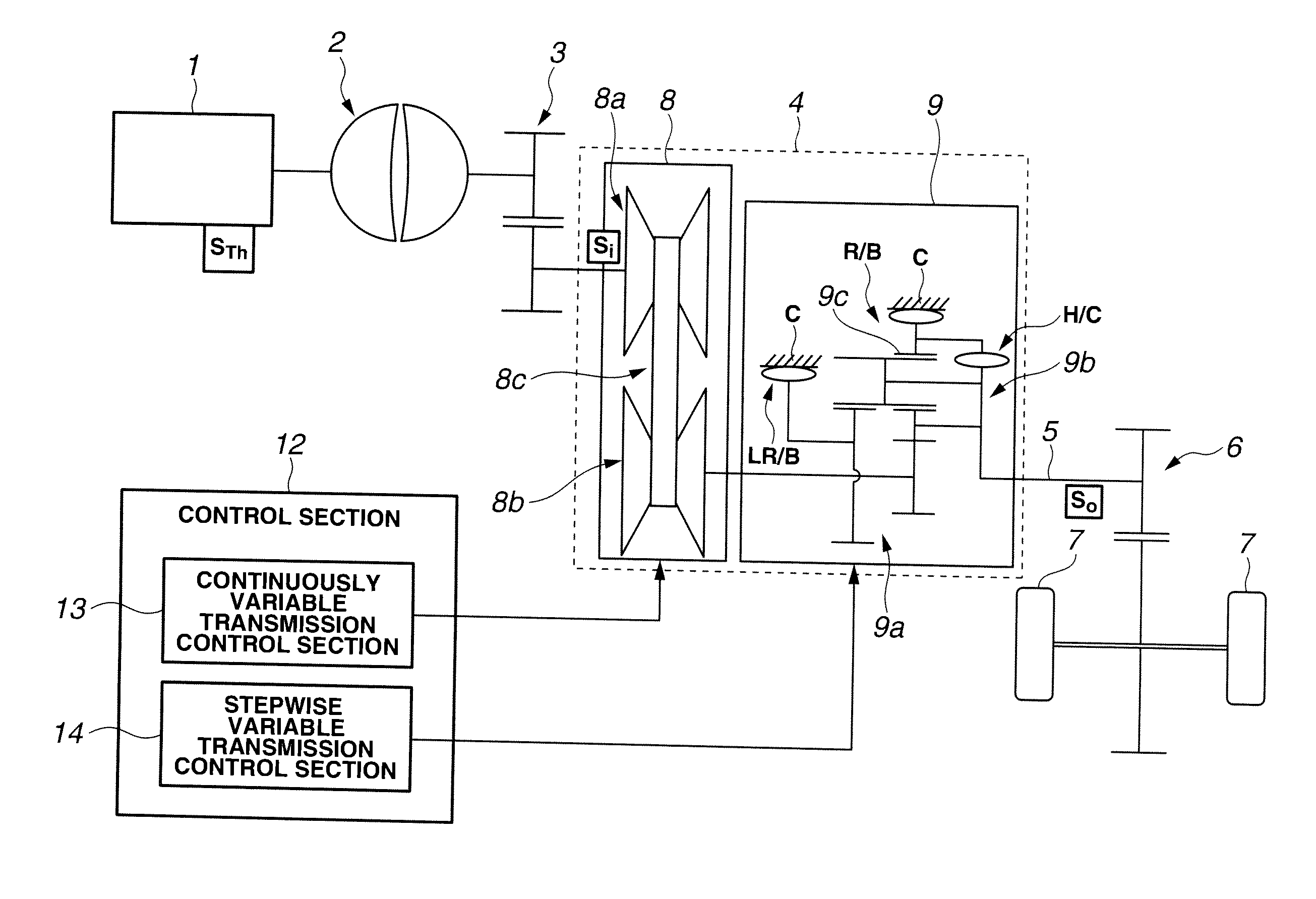
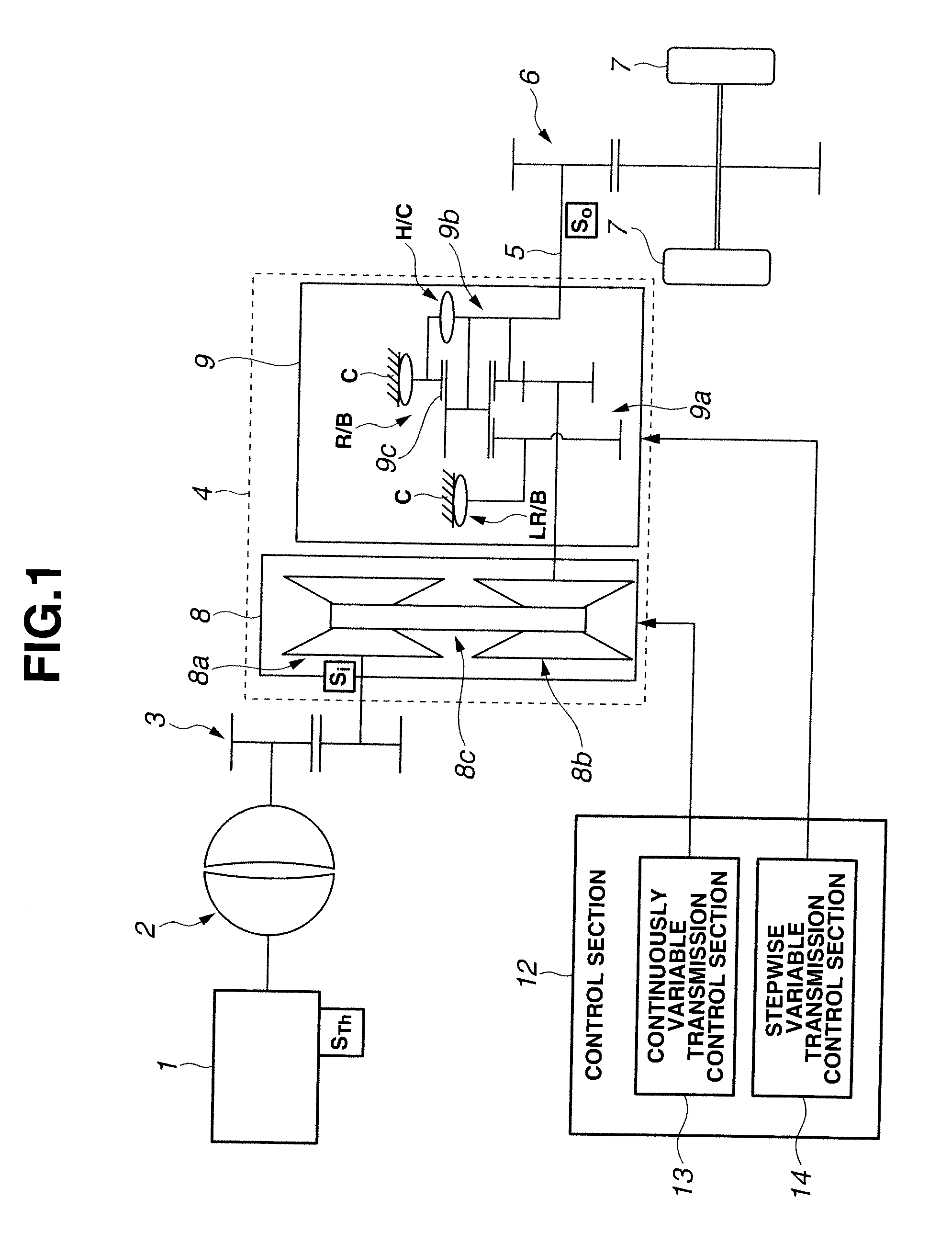
[0024]FIG. 1 is a schematically explanatory diagram showing a part of a construction of a vehicle including a control apparatus for an automatic transmission system, according to a first embodiment of the present invention. As illustrated in FIG. 1, drive system 1 includes engine 1 as a drive source, torque converter 2 drivingly connected to engine 1, automatic transmission system 4 drivingly connected to torque converter 2 via reduction mechanism 3, final drive gear mechanism 6 drivingly connected to automatic transmission system 4 via transmission output shaft (i.e., propeller shaft) 5, and road wheels 7 to which a power from automatic transmission system 4 is outputted via final drive gear mechanism 6.

[0025]Automatic transmission system 4 is constituted of continuously variable transmission mechanism 8 and stepwise variable transmission mechanism 9. Continuously variable transmission mechanism 8 is a known belt-drive continuously variable transmission and includes drive pulley 8a...

second embodiment

[0067]In the second embodiment, in automatic transmission system 4 that has the serial arrangement of continuously variable transmission mechanism (CVT) 8 and stepwise variable transmission mechanism (AT) 9 and performs the cooperative shift control as described above, in a case where the response of stepwise variable transmission mechanism (AT) 9 is delayed as compared to the response of continuously variable transmission mechanism (CVT) 8, the shift control of continuously variable transmission mechanism (CVT) 8 and the shift control of stepwise variable transmission mechanism (AT) 9 are respectively performed as follows.

[0068]

[0069]The target stepwise variable transmission ratio is set, and then shift control of the stepwise variable transmission mechanism is performed on the basis of the set target stepwise variable transmission ratio.

[0070]

[0071]The target stepwise variable transmission ratio set above is subjected to a retardation processing to set a retardation-processed targ...


PUM


Abstract

A control apparatus for an automatic transmission system having a serial arrangement of a stepwise variable automatic transmission mechanism and a continuously variable automatic transmission mechanism, the control apparatus being disposed in the automatic transmission system and performing a shift control of the continuously variable automatic transmission mechanism in accordance with variation in transmission ratio of the stepwise variable automatic transmission mechanism, the control apparatus including a control section configured to execute a retardation processing upon shift control of one of the continuously variable transmission mechanism and the stepwise variable transmission mechanism which has a smaller response delay of an actual transmission ratio from a target transmission ratio than that of the other transmission mechanism.

Description

BACKGROUND OF THE INVENTION[0001]The present invention relates to a control apparatus and method for an automatic transmission system having a serial arrangement of a continuously variable transmission (or a continuously variable transmission mechanism) and a stepwise variable transmission (or a stepwise variable transmission mechanism), which is capable of performing cooperative shift control in which shift of the continuously variable transmission is controlled in accordance with a change in transmission ratio of the stepwise variable transmission.[0002]Japanese Patent Application First Publication No. 5-079554 discloses an automatic transmission system for a vehicle in which a continuously variable transmission and a stepwise variable transmission are arranged in series. In the conventional art, upon carrying out a shift operation of the stepwise variable transmission, cooperative shift control is conducted, in which shift control of the stepwise variable transmission and shift c...

Claims


Application Information

Patent Timeline
IPC IPC(8): G06F19/00F16H59/68F16H61/04F16H61/66F16H61/662F16H61/68F16H61/684F16H61/686
CPCF16H37/022F16H61/08F16H61/66259F16H61/702Y10T477/735F16H2061/085Y10T477/6414Y10T477/26F16H2037/023F16H37/00F16H37/02F16H61/00F16H61/04
Inventor TAKAHASHI, SEIICHIROOCHIAI, TATSUOUCHIDA, MASAAKIKOGA, MASATOKADONO, RYOJIJOZAKI, TATEKISUZUKI, HIDEAKINONOMURA, RYOUSUKEINOUE, MAMIKO
Owner NISSAN MOTOR CO LTD
Why Eureka
Try Eureka