Diesel aftertreatment systems

a technology of aftertreatment system and diesel, which is applied in the direction of engines, mechanical equipment, machines/engines, etc., can solve the problems of ineffective prior art urea injection system, inability to achieve optimal system efficiency, and disadvantages of this approach

Inactive Publication Date: 2005-05-24
FORD GLOBAL TECH LLC
View PDF97 Cites 41 Cited by
  • Summary
  • Abstract
  • Description
  • Claims
  • Application Information

AI Technical Summary

Benefits of technology

[0007]The above advantages and other advantages, objects and features of the present invention will be readily apparent fr

Problems solved by technology

The inventors herein have recognized a disadvantage with this approach.
Namely, optimum system efficiency is not achieved unless the injected aqueous urea is well distributed and atomized and has sufficient time in the exhaust gas to complete conversion into gaseous ammonia prior to reaching SCR catalyst brick face.
The inventors

Method used


Image

  • Diesel aftertreatment systems
  • Diesel aftertreatment systems
  • Diesel aftertreatment systems

Examples


Embodiment Construction

)

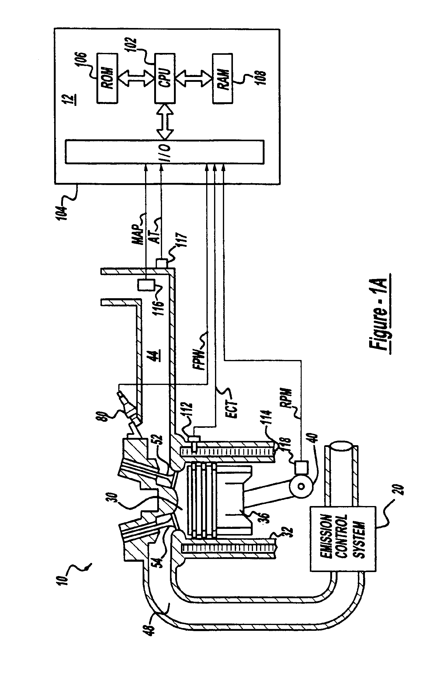
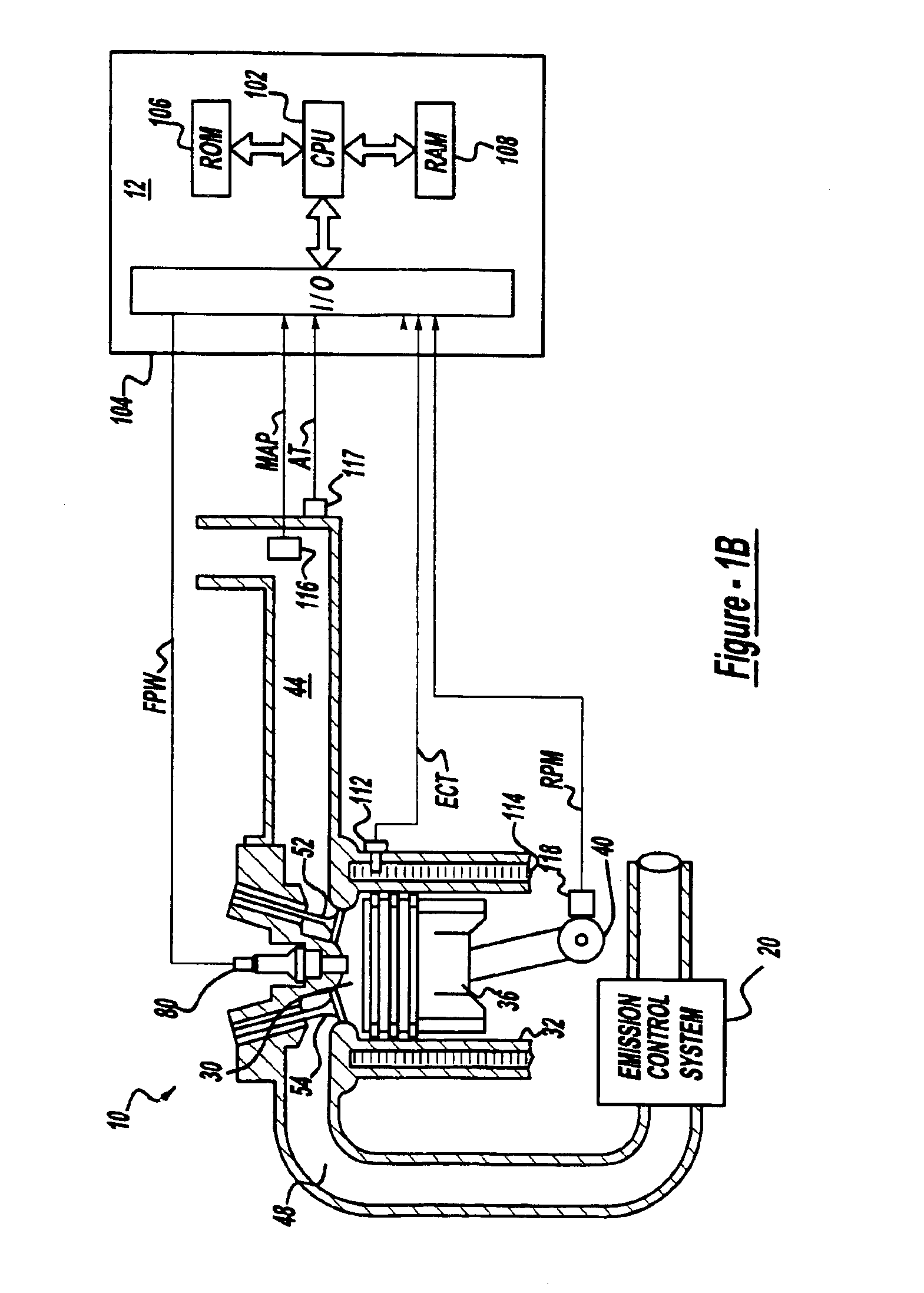
[0014]Internal combustion engine 10, comprising a plurality of cylinders, one cylinder of which is shown in FIG. 1, is controlled by electronic engine controller 12. Engine 10 includes combustion chamber 30 and cylinder walls 32 with piston 36 positioned therein and connected to crankshaft 40. Combustion chamber 30 is shown communicating with intake manifold 44 and exhaust manifold 48 via respective intake valve 52 and exhaust valve 54. Intake manifold 44 is also shown having fuel injector 80 coupled thereto for delivering liquid fuel in proportion to the pulse width of signal FPW from controller 12. Both fuel quantity, controlled by signal FPW and injection timing are adjustable. Fuel is delivered to fuel injector 80 by a fuel system (not shown) including a fuel tank, fuel pump, and fuel rail (not shown).

[0015]Controller 12 is shown in FIG. 1 as a conventional microcomputer including: microprocessor unit 102, input / output ports 104, read-only memory 106, random access memory 108, ...


PUM


Abstract

A method and a system for improving conversion efficiency of a urea-based SCR catalyst coupled downstream of a diesel or other lean burn engine is presented. The system includes an electrically heated vaporizer unit into which a mixture of reductant and air in injected. The mixture is vaporized in the unit and introduced into the exhaust gas prior to its entering the SCR catalyst. Introducing the reductant mixed with air into the reductant delivery system prevents lacquering and soot deposits on the heated element housed inside the unit, and also speeds up the vaporization process thus reducing system response delays and improving the device conversion efficiency. The reductant delivery system is further improved by adding a hydrolyzing catalyst to it, and by isolating the reductant and air mixture from the heating element.

Description

FIELD OF INVENTION[0001]The present invention relates to a system and a method for improving performance of an exhaust gas aftertreatment device, and more particularly to using an air assist heated reductant delivery system to enhance system performance and reduce fuel penalty.BACKGROUND OF THE INVENTION[0002]Current emission control regulations necessitate the use of catalysts in the exhaust systems of automotive vehicles in order to convert carbon monoxide (CO), hydrocarbons (HC), and nitrogen oxides (NOx) produced during engine operation into harmless exhaust gasses. Vehicles equipped with diesel or lean gasoline engines offer the benefits of increased fuel economy. Such vehicles have to be equipped with lean exhaust aftertreatment devices such as, for example, a urea-based Selective Catalytic Reduction (SCR) catalyst, which is capable of continuously reducing NOx emissions, even in an oxygen rich environment. Urea-based SCR catalysts use gaseous ammonia as the active NOx reducin...

Claims


Application Information

Patent Timeline
IPC IPC(8): F01N3/20F01N3/30F01N3/28F01N7/00F01N3/32F01N7/02F02B75/12F02B75/00F01N13/02
CPCF01N3/2066F01N13/009F01N3/2896F01N3/32F01N2240/16F01N2240/20F01N2240/40F01N2250/02F01N2370/04F01N2570/14F01N2610/02F01N2610/08F01N2610/10F01N2610/107F01N2610/1453F02B2075/125Y02T10/123Y02T10/24Y02T10/12
Inventor UPADHYAY, DEVESHGOEBELBECKER, MICHAELVAN NIEUWSTADT, MICHIEL J.RUONA, WILLIAM CHARLES
Owner FORD GLOBAL TECH LLC
Why Eureka
Try Eureka