Driver unit with a thrust washer and method for manufacturing the same

Inactive Publication Date: 2010-09-09
ROBERT BOSCH GMBH
View PDF13 Cites 8 Cited by
  • Summary
  • Abstract
  • Description
  • Claims
  • Application Information

AI Technical Summary

Benefits of technology

[0011]When the drive is operated in both directions of rotation, high axial loads occur on both end faces of the drive shaft. Two identica

Problems solved by technology

In addition, with a servo unit of this type, there is a risk that the amount of lubricant on the friction surface between the thrust washer an

Method used


Image

  • Driver unit with a thrust washer and method for manufacturing the same
  • Driver unit with a thrust washer and method for manufacturing the same
  • Driver unit with a thrust washer and method for manufacturing the same

Examples


Embodiment Construction

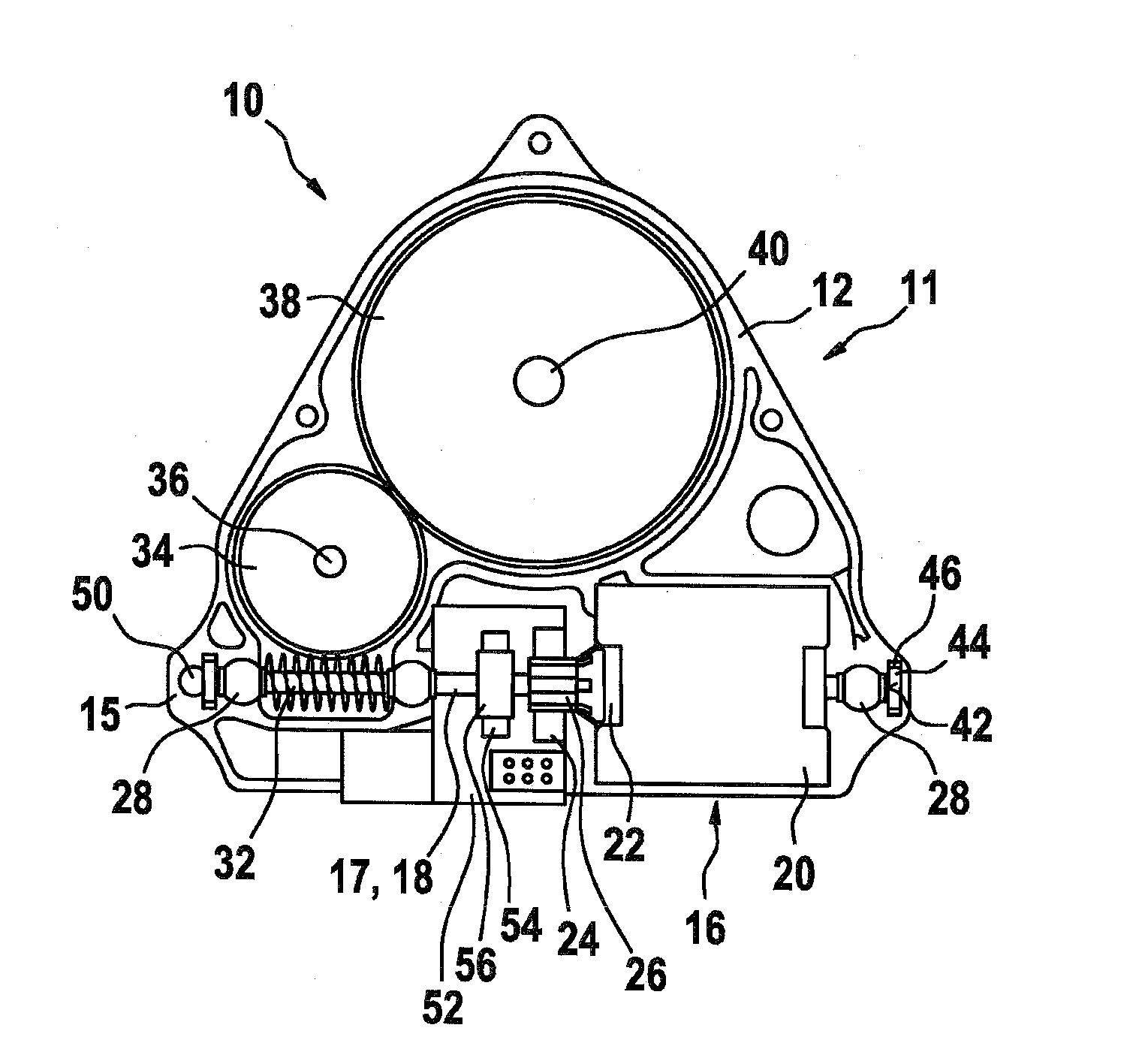
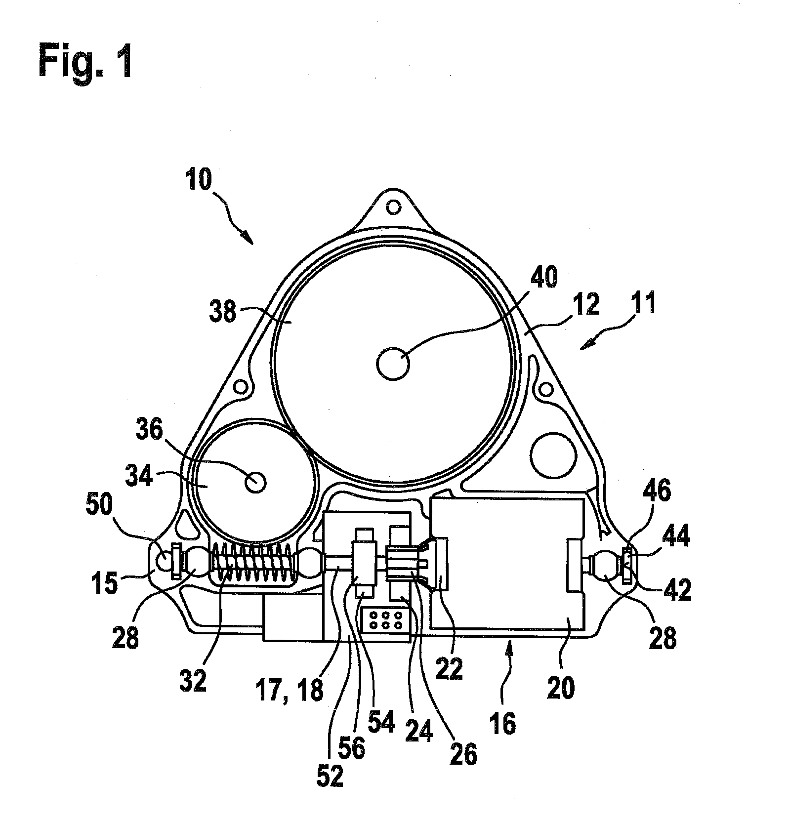
[0016]FIG. 1 shows a drive unit 10, with which an electric motor 16 with a drive shaft 17 is located in a first housing part 12 of a housing 11. Electric motor 16 includes permanent magnets 20, which are non-rotatably mounted in housing 11 and set an armature 22 into rotation. Armature 22 is commutated via a collector 26, using brushes 24. An electronics unit 52 is located in the region of a collector 26, which registers a position signal of a signal transducer 56 using a sensor system 54. Bearings 28 are located on drive shaft 17, which is designed as an armature shaft 18. Bearings 28 are inserted, e.g., directly in related bearing receptacles 30 in housing 11. Armature shaft 18 also includes a worm 32, which meshes with a worm gear 34 located on a first bearing axis 36. In a further gear stage, torque is transferred from worm gear 34 to an output element 38 located on a second axis 40. Drive shaft 17 is inserted with its entire length radially into first housing part 12. Drive sha...


PUM


Abstract

The invention relates to a drive unit (10) and to a method for producing the same, in particular for adjusting moveable parts in a motor vehicle, having a metal driveshaft (17) which is mounted in a housing (11) by means of at least one radial bearing element (28), wherein the driveshaft (17) has two end sides (42), at least one of which, as an axial stop, is supported on the housing (11) by means of a stop disk (44), wherein the stop disk (44) is produced from a self-lubricating material (49) which lubricates the axial stop over the entire service life of the drive unit (10) without the use of additional, separate lubricants.

Description

RELATED ART[0001]The present invention relates to a drive unit, in particular for adjusting movable parts in a motor vehicle, and a method for manufacturing such a drive unit with a thrust washer for the drive shaft, according to the one of the independent claims.[0002]Publication DE 102 35 365 A1 made known a servo unit, in the case of which an electric motor drives an armature shaft. A worm is located on the armature shaft, which meshes with a worm gear and provides output torque to a driven pinion. The armature shaft is supported axially at its end faces via thrust washers, relative to which the cap-shaped ends of the armature shaft rotate. To minimize the wear of the thrust washers, the cap-shaped ends of the armature shaft are optimized. With this servo unit, the thrust washers are installed axially into related receptacles in the pole pot or the transmission housing. To minimize the friction between the stop caps and the thrust washers, grease is deposited in these receptacles...

Claims


Application Information

Patent Timeline
IPC IPC(8): F16H1/16H02K7/116F16H57/021
CPCF16C17/08F16C33/201F16H57/021Y10T74/19828H02K7/1166F16H2057/0213F16C2380/27H02K7/081F16H57/023F16H57/02F16H57/04
Inventor HUCK, THOMASMILI, TAREKBUEYUEKASIK, DIYAPLAMPERT, RICO
Owner ROBERT BOSCH GMBH
Why Eureka
Try Eureka