Sheet Feeder And Image Forming Apparatus Including Same

a feeder and image technology, applied in the field of feeders, can solve the problems of downsizing the feeder, affecting the operation, and causing the noise of the primary source of the operation, so as to achieve quiet operation and reduce the effect of spa

Inactive Publication Date: 2010-09-09
RICOH KK
View PDF12 Cites 13 Cited by
  • Summary
  • Abstract
  • Description
  • Claims
  • Application Information

AI Technical Summary

Benefits of technology

[0012]In this disclosure, a sheet feeder employing a one-revolution clutch system using a drive

Problems solved by technology

In most image forming apparatuses, a manual sheet feeder accessible to users is often provided external to the main body of the image forming apparatuses, and is thus a prime source of much operating noise.
However, in the above-described configuration, the spring is required to have a large force to rotate the sheet feed shaft and the sheet feed roller and to vertically move the bottom plate.
Consequently, both impact energy applied to the drive gear from the chipped tooth gear when the drive gear and the chipped tooth gear mesh with each other at the start of sheet feeding as well as the force of impact caused by engagement of the solenoid flapper with the disk member wh

Method used


Image

  • Sheet Feeder And Image Forming Apparatus Including Same
  • Sheet Feeder And Image Forming Apparatus Including Same
  • Sheet Feeder And Image Forming Apparatus Including Same

Examples


Embodiment Construction

[0041]In describing illustrative embodiments illustrated in the drawings, specific terminology is employed for the sake of clarity. However, the disclosure of this patent specification is not intended to be limited to the specific terminology so selected and it is to be understood that each specific element includes all technical equivalents that operate in a similar manner and achieve a similar result.

[0042]Illustrative embodiments of the present invention are described in detail below. It is to be noted that the present invention is applicable to various devices performing image formation in addition to the image forming apparatus that is described below.

[0043]A description is now given of a first illustrative embodiment of the present invention.

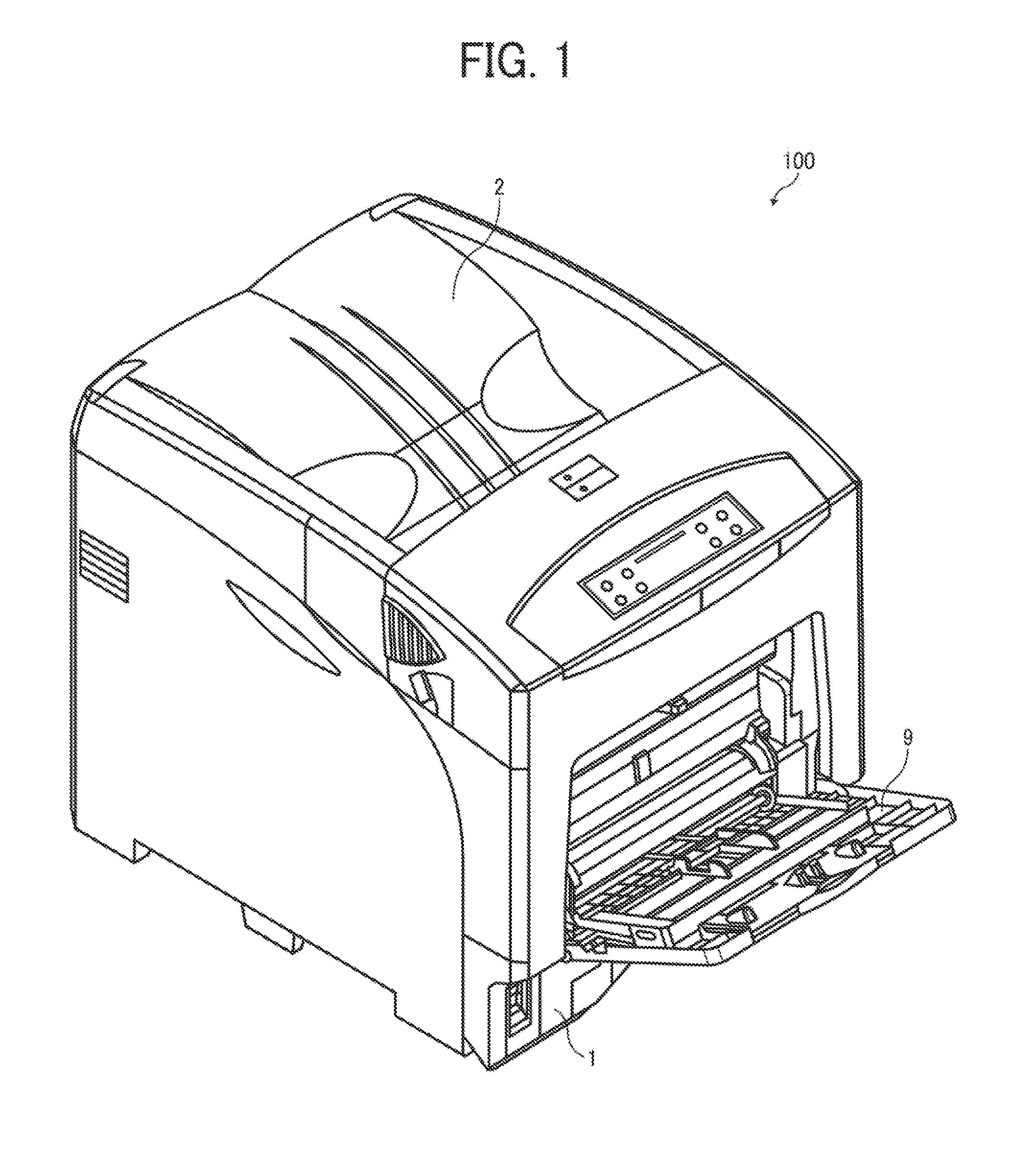
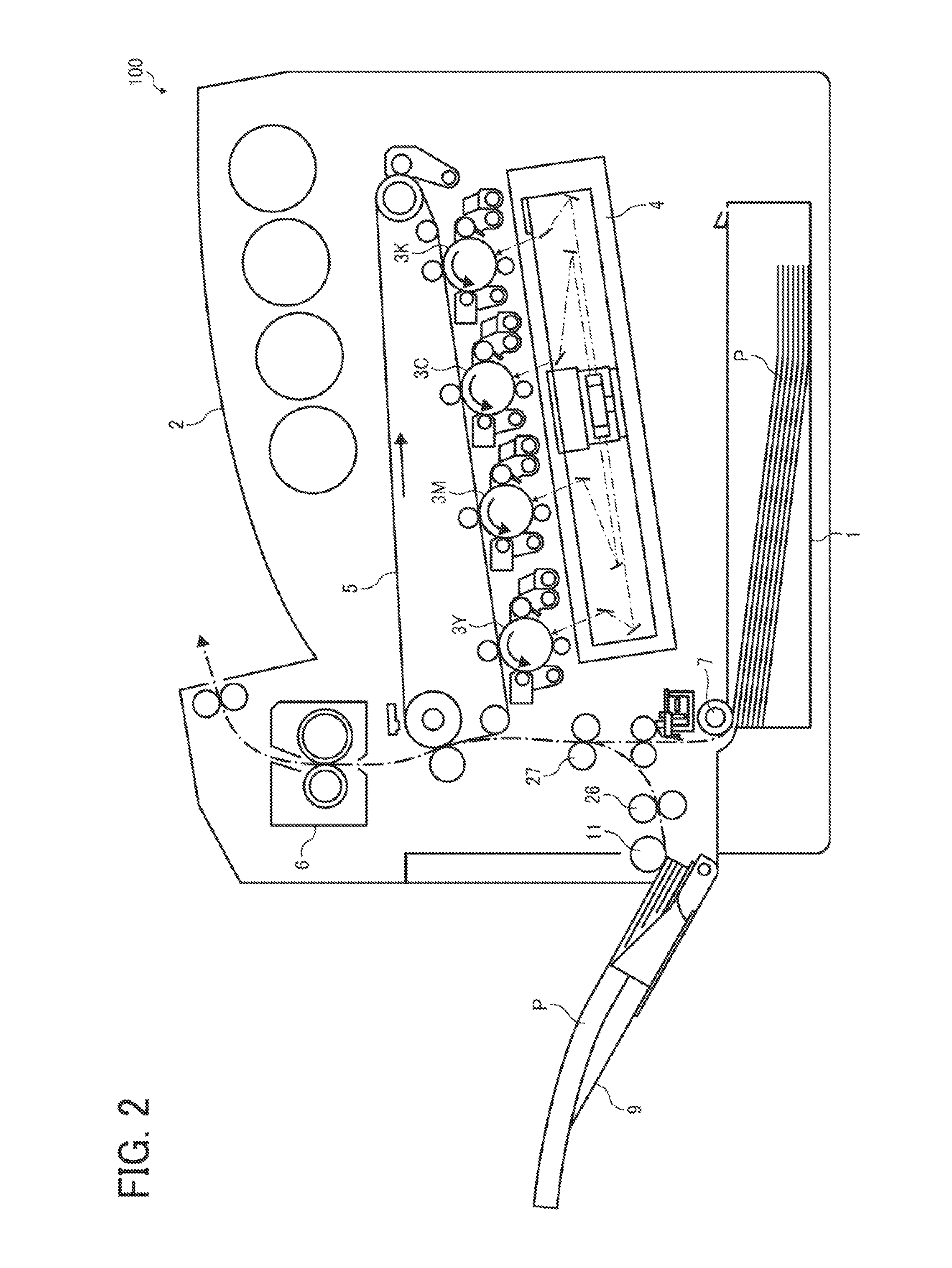
[0044]FIG. 1 is a perspective view illustrating an appearance of a laser printer serving as an image forming apparatus 100 according to illustrative embodiments. FIG. 2 is a vertical cross-sectional view illustrating a configuration of the...


PUM


Abstract

A sheet feeder including a sheet feed shaft, a partially cut-out semicircular sheet feed roller coaxially provided to the sheet feed shaft, a cam coaxially provided to the sheet feed shaft, a driven gear having a toothless portion coaxially provided to the sheet feed shaft, a bottom plate movable to contact or separate from the cam, a driving unit to move the driven gear relative to the sheet feed shaft in a direction of rotation of the sheet feed shaft, a drive gear to drive the driven gear, a gear stopping unit to stop rotation of the driven gear at a predetermined timing, a coupling unit to drive the driven gear and the sheet feed shaft in conjunction with each other, and a shaft stopping unit to stop rotation of the sheet feed shaft.

Description

BACKGROUND[0001]1. Technical Field[0002]This disclosure relates to a sheet feeder employed in an image forming apparatus, and an image forming apparatus including the sheet feeder.[0003]2. Description of the Background[0004]Increasingly, quieter operation is required of image forming apparatuses such as copiers, printers, or multifunction devices having copying and printing functions. In particular, because clients of end users of the image forming apparatuses are often present in the same space where the image forming apparatuses are installed and used, in medical facilities, retail stores, and so forth, noise reduction is strongly demanded.[0005]In most image forming apparatuses, a manual sheet feeder accessible to users is often provided external to the main body of the image forming apparatuses, and is thus a prime source of much operating noise. Moreover, in addition to noise reduction during operation, a simple, inexpensive configuration is also sought for such manual sheet fe...

Claims


Application Information

Patent Timeline
IPC IPC(8): B65H5/06F16H57/10
CPCB65H3/0607B65H3/0669B65H2403/421Y10T74/19637B65H2403/721B65H2403/725B65H2404/1112B65H2403/512
Inventor NAKAMURA, MITSUTAKAFUJIWARA, HIDEHIKO
Owner RICOH KK
Why Eureka
Try Eureka