
Seating structure and method of making same

a technology of sat-shaped structure and sat-shaped body, which is applied in the direction of automotive seats, transportation and packaging, ceramic shaping apparatus, etc., can solve the problems of unfavorable adaptability to the various flexibility requirements, undesired rigidity at the different elastic areas, and inability to meet the various flexibility requirements. , to achieve the effect of high efficiency and cost-effectiveness

Inactive Publication Date: 2010-09-09
SELLE ROYAL SPA
View PDF19 Cites 10 Cited by
  • Summary
  • Abstract
  • Description
  • Claims
  • Application Information

AI Technical Summary

Benefits of technology

[0018]The object of the present invention is to overcome the above drawbacks, by providing a seating structure that is highly efficient and relatively cost-effective.
[0019]A particular object is to provide a seating structure having differently deformable areas that is particularly safe for the user and capable of withstanding the stresses generated during riding.
[0022]Yet another object is to provide a method that ensures high cost-effectiveness and efficiency.

Problems solved by technology

A similar shell type has a substantially uniform resilience throughout its structure and is thus not easily adaptable to the various flexibility requirements associated with the various parts of the cyclist's seat.
Nonetheless, this prior art solution suffers from certain apparent drawbacks, particularly in that the protective rim so formed is substantially continuous and homogeneous and causes undesired rigidity at the differently elastic areas.
Furthermore, overmolding is not always a cost-effective process, due to the relatively high cost of the mold.
One drawback of this prior art solution is that the strength of the individual rim portions might not be well defined at the interface between the different co-injected materials.
As a result, the areas at the contact surfaces might exhibit “hybrid” mechanical properties, which might cause uneven reaction of the shell to the stresses generated during riding, and involve the risk of failure at such areas.

Method used


Image

  • Seating structure and method of making same
  • Seating structure and method of making same
  • Seating structure and method of making same

Examples


Embodiment Construction

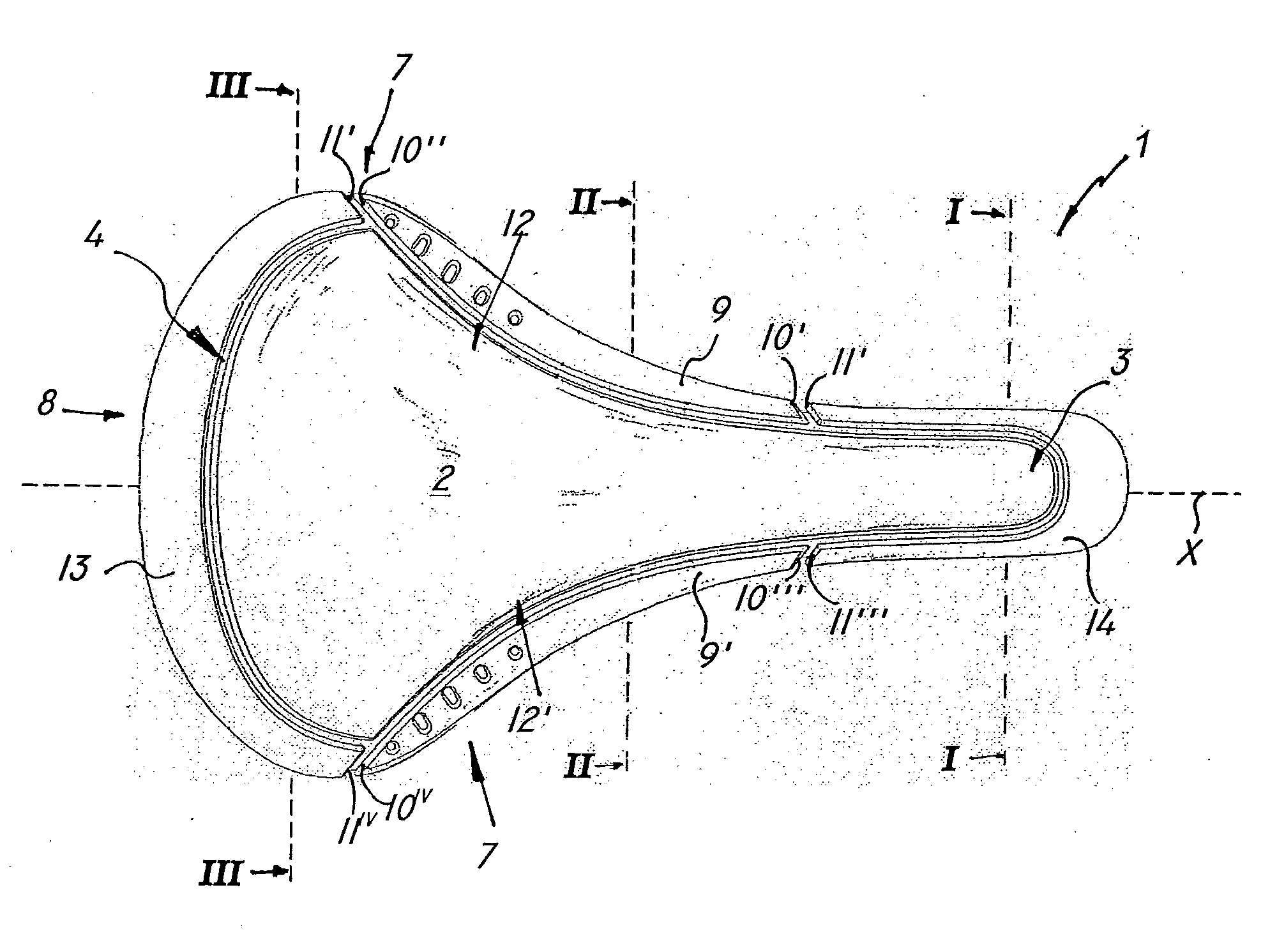
[0039]Referring to the above figures, the seating structure of the invention, generally designated by numeral 1, may be a bicycle saddle structure connected in a per se known manner to rails or similar supports, not shown, for attachment to a movable or stationary frame, also not shown. Nonetheless, it will be understood that the seating structure 1 may be configured as a seat, a seating surface of a chair or any other human body support.

[0040]The structure 1 may be also associated with an upper cover, not shown but known per se, possibly having a pad or another layer of resilient material for improved seating comfort.

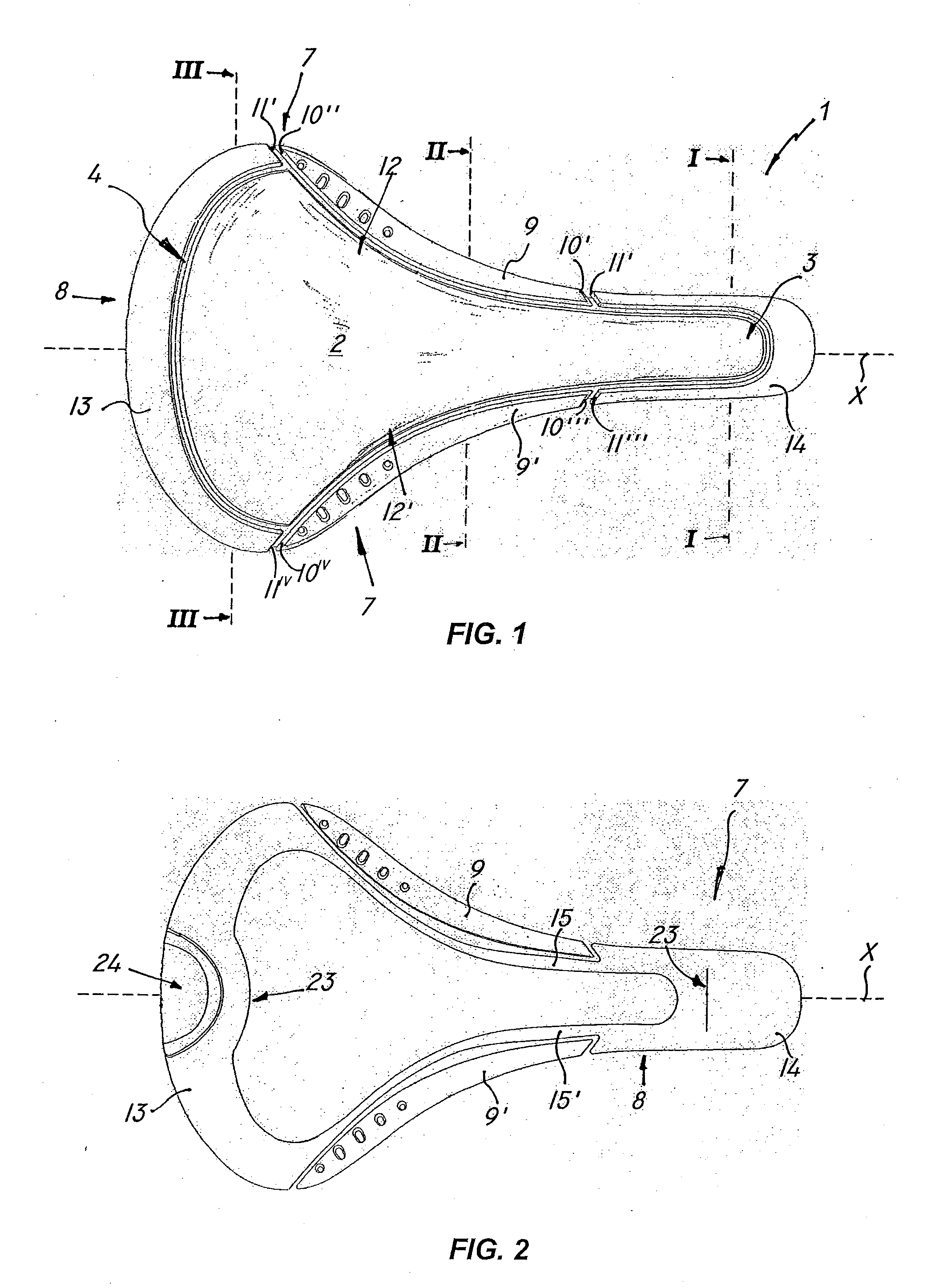
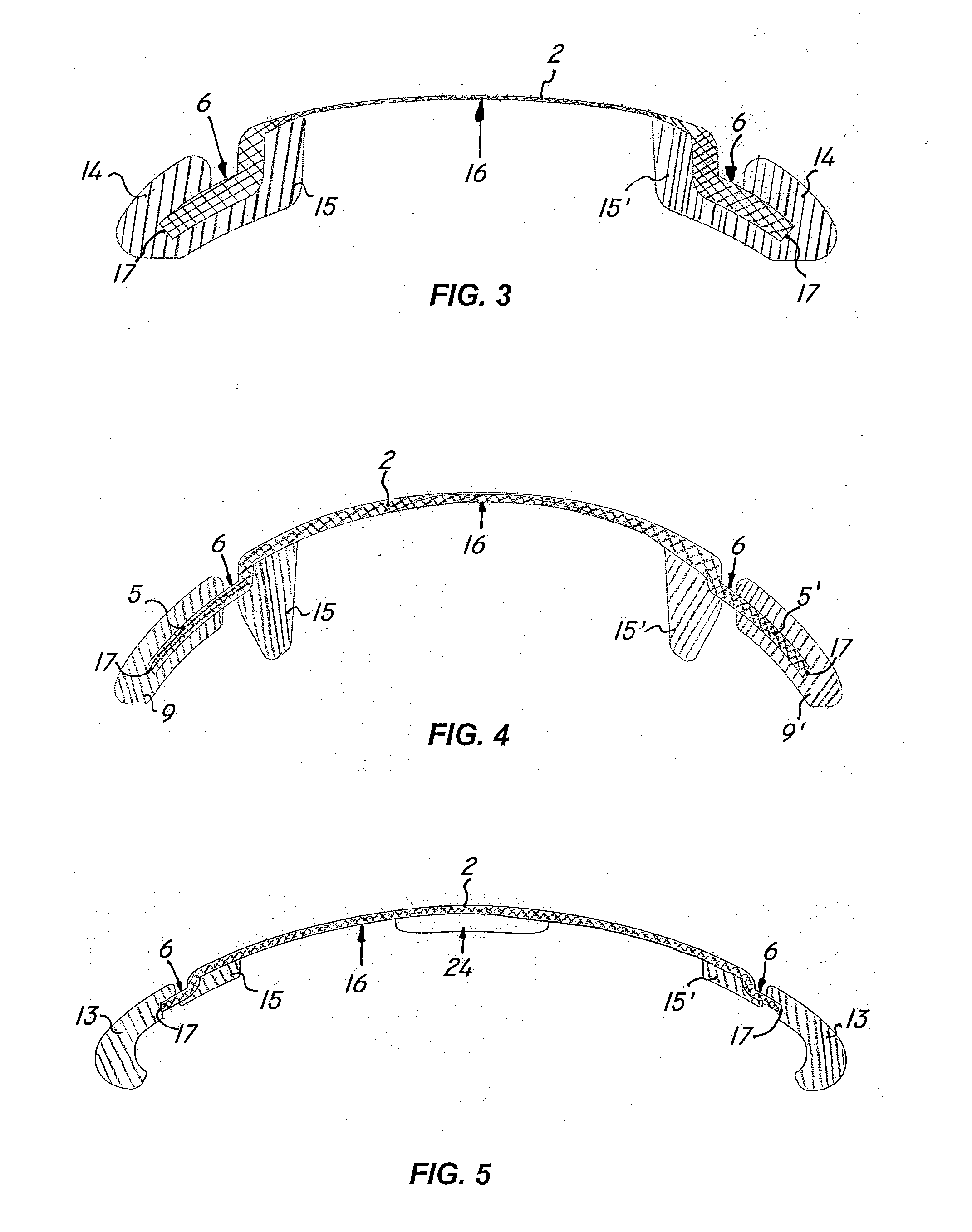
[0041]According to the invention, the seating structure, as shown in FIG. 1, comprises a load-bearing shell 2 with an elongate front portion 3 defining a longitudinal axis X, a widened rear portion 4 and at least one differently deformable portion 5, as compared with the rest of the shell 2, which is formed proximate to the outer periphery 6 thereof.

[0042]A substantial...


PUM

PropertyMeasurementUnit
Timeaaaaaaaaaa
Structureaaaaaaaaaa
Stiffnessaaaaaaaaaa

Abstract

A seating structure, particularly for bicycle saddles, includes a load-bearing shell with at least one differently deformable portion proximate to its outer periphery, a substantially annular protective rim with a first portion formed of a first material of predetermined elastic rigidity and at least one second portion formed of a second base material having a different elastic rigidity from that of said first material. The second portion is located at said at least one differently deformable portion and is separated from said first portion to define at least one substantially transverse end wall facing towards and distinct from at least one respective end wall of said first portion. A method is provided for making a seating structure as above.

Description

BACKGROUND TECHNICAL FIELD[0001]The present invention generally finds application in the technical field of sport and leisure accessories, and specifically relates to a seating structure, such as for a bicycle saddle, and a method of making same.DESCRIPTION OF RELATED ART[0002]Human body seating structures, such as chairs, seats, bicycle saddles and the like, are known to be comprised by a load-bearing structure including a user-supporting shell, which is designed to be attached to a support frame.[0003]The shell has the basic purpose of supporting a seated user while ensuring comfort. It shall also have a particularly low weight to provide easy riding.[0004]According to a prior art solution, shells may be constituted by one or more sheets of composite materials, which are joined together by bonding or molding and later curing and / or polymerization of the resin.[0005]A similar shell type has a substantially uniform resilience throughout its structure and is thus not easily adaptable...

Claims


Application Information

Patent Timeline
IPC IPC(8): B62J1/02B29C45/16
CPCB62J1/00
Inventor SEGATO, STEFANO
Owner SELLE ROYAL SPA
Learn More