Rotor having embedded permanent magnet

Active Publication Date: 2010-09-09
HYUNDAI MOTOR CO LTD +2
View PDF9 Cites 12 Cited by
  • Summary
  • Abstract
  • Description
  • Claims
  • Application Information

AI Technical Summary

Benefits of technology

[0011]In one aspect, the present invention is directed to a rotor for a hybrid car, particularly where the preferred structure of arranging a permane

Problems solved by technology

IPM motors as described in the art can obtain suitably high torque owing to a substantially U-shaped arrangement of the magnets, but the diameter of the rotor needs to be suitably increased making it difficult to make them compact.
Accordingly, the rotor core thereof has a circular hollow section with the ce

Method used


Image

  • Rotor having embedded permanent magnet
  • Rotor having embedded permanent magnet
  • Rotor having embedded permanent magnet

Examples


Example

[0027]As described herein, the present invention includes a magnet-embedded rotor in a motor comprising planar permanent magnets, wherein the magnets are circumferentially arranged at regular intervals in a cylindrical rotor core, and wherein electrolytic galvanized iron plates are laminated on one another.

[0028]In one embodiment, the outer circumferential surfaces of the permanent magnets are arranged so as to become alternating poles of N and S.

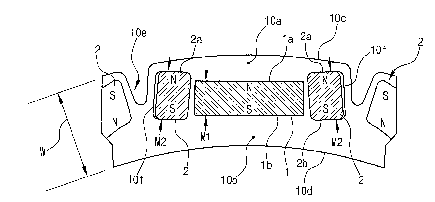
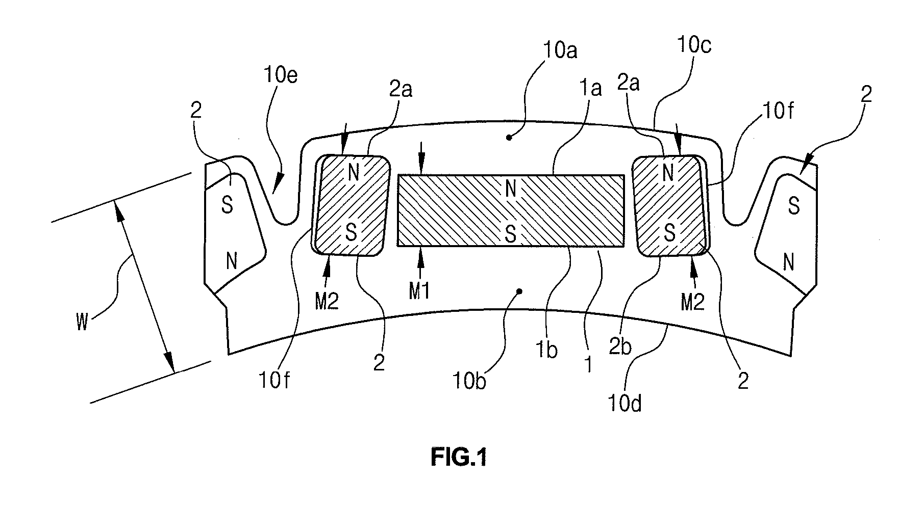
[0029]In one embodiment, the permanent magnets further comprise a 3-part arrangement including a center magnet and two side magnets.

[0030]In another embodiment, the width of a polar surface of each side magnet is smaller than that of the center magnet.

[0031]In another further embodiments, the magnets are embedded in the rotor core so as to be parallel with a tangential line thereof, and a width between both poles of the center magnet is smaller than those of the side magnets, and a volume of the pole-front side core from an outer circumfere...


PUM


Abstract

A structure for arranging a permanent magnet suitable for a rotor core having a thin, circular, hollow ring section and a structure for reducing the amount of the permanent magnet are provided.

Description

CROSS-REFERENCE TO RELATED APPLICATION[0001]This application claims the benefit of Japanese Patent Application No. 2009-053240, filed on Mar. 6, 2009, the entire disclosure of which is hereby incorporated by reference.BACKGROUND OF THE INVENTION[0002]1. Field of the Invention[0003]The present invention relates, in general, to a rotor having an embedded permanent magnet, and more particularly, to a structure comprising a permanent magnet suitable for a rotor core preferably having a thin, circular, hollow section and a structure which suitably reduces the amount of permanent magnet.[0004]2. Description of the Related Art[0005]Generally, a synchronous motor using a permanent magnet (or a magnet) preferably includes a surface permanent magnet (SPM) type motor in which a permanent magnet is suitably attached onto the surface of a rotor, and an interior permanent magnet (IPM) type motor in which a permanent magnet is suitably embedded into a core of a rotor. The IPM type motor is general...

Claims


Application Information

Patent Timeline
IPC IPC(8): H02K1/27
CPCH02K1/2766H02K1/27H02K1/28
Inventor HIROSHI, NISHIMURA
Owner HYUNDAI MOTOR CO LTD
Why Eureka
Try Eureka