Steel having non-magnetic portion, its producing method, and revolving electric core

Inactive Publication Date: 2010-09-09
TOYOTA JIDOSHA KK
View PDF9 Cites 10 Cited by
  • Summary
  • Abstract
  • Description
  • Claims
  • Application Information

AI Technical Summary

Benefits of technology

[0028]According to the invention, there is provided a steel having a nonmagnetic portion, applicable irrespective of the steel species of other portions than the n

Problems solved by technology

However, the core includes some portions that will not form any effective magnetic paths due to placement of coils and magnets.
However, because o

Method used


Image

  • Steel having non-magnetic portion, its producing method, and revolving electric core
  • Steel having non-magnetic portion, its producing method, and revolving electric core
  • Steel having non-magnetic portion, its producing method, and revolving electric core

Examples


Example

First Embodiment

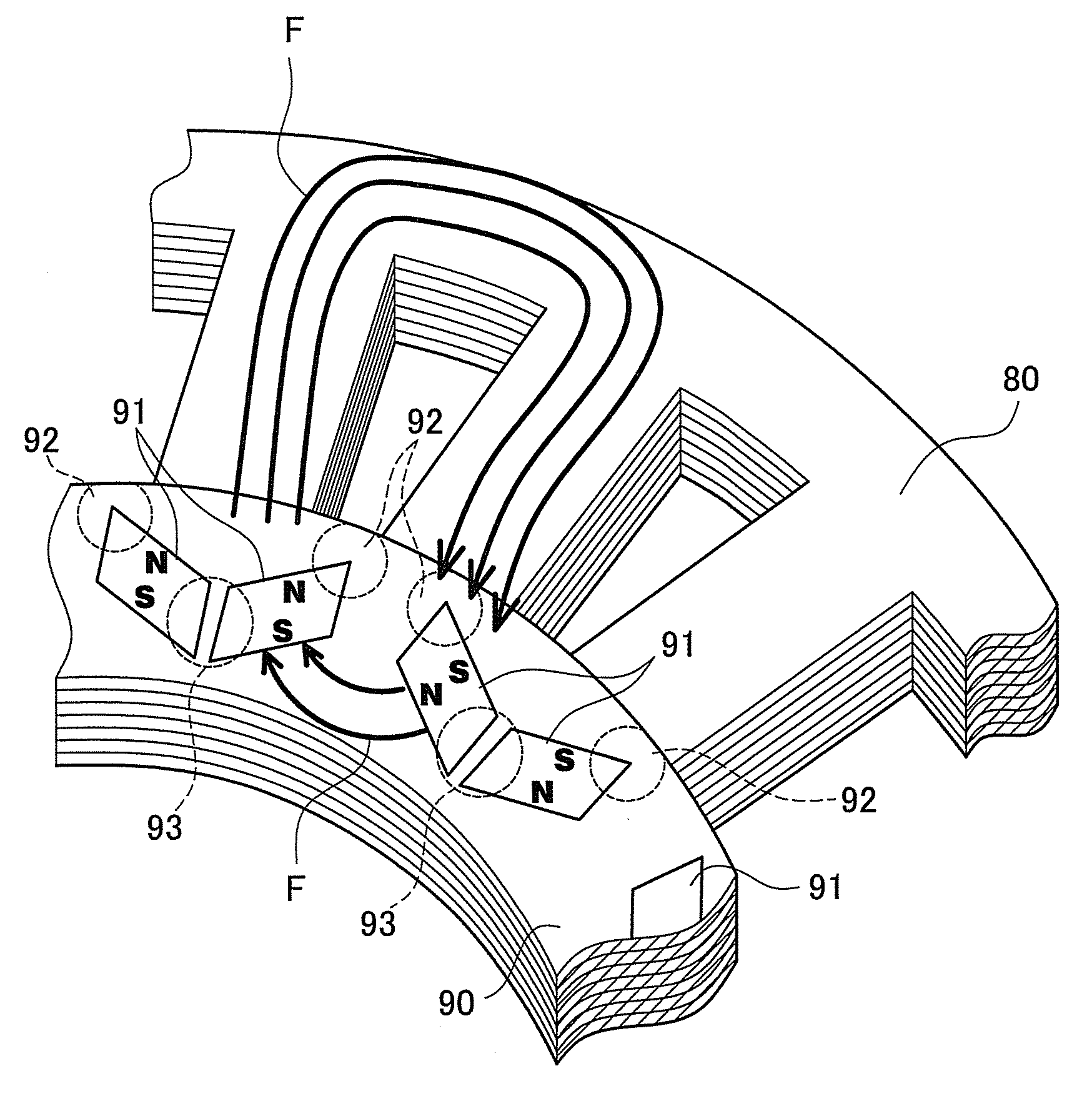
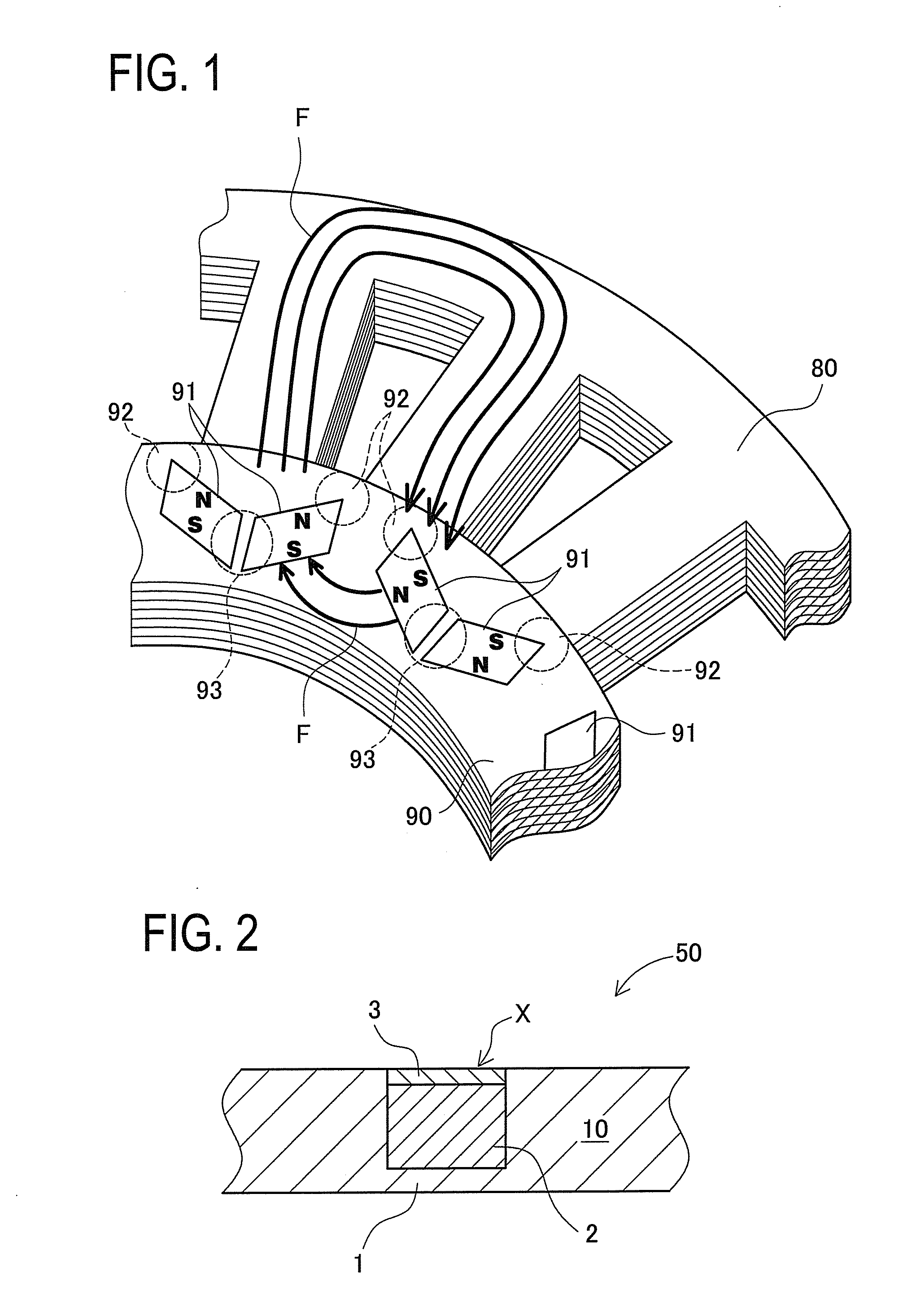
[0084]A detailed description of preferred embodiments of the present invention will now be given referring to the accompanying drawings. A revolving electric machine in this embodiment includes nonmagnetic portions made by the steps explained below as peripheral bridge portions 92 and central bridge portions 93 of a rotor 90 shown in FIG. 1. Each central bridge portion 93 is a portion located between adjacent magnet-mounting holes. Each peripheral bridge portion 92 is a portion located between a magnet-mounting hole and an outer circumferential edge. Each of the rotor 90 and a stator 80 is made of a number of laminated electromagnetic steel sheets.

[0085]A structure of nonmagnetic portions in the rotor 90 in this embodiment is first explained. Each nonmagnetic portion in the rotor 90 has a cross section shown in FIG. 2. FIG. 2 is a sectional view of an electromagnetic steel sheet 50 including the nonmagnetic portion in the rotor 90. A nonmagnetic portion X in FIG. 2 i...

Example

Second Embodiment

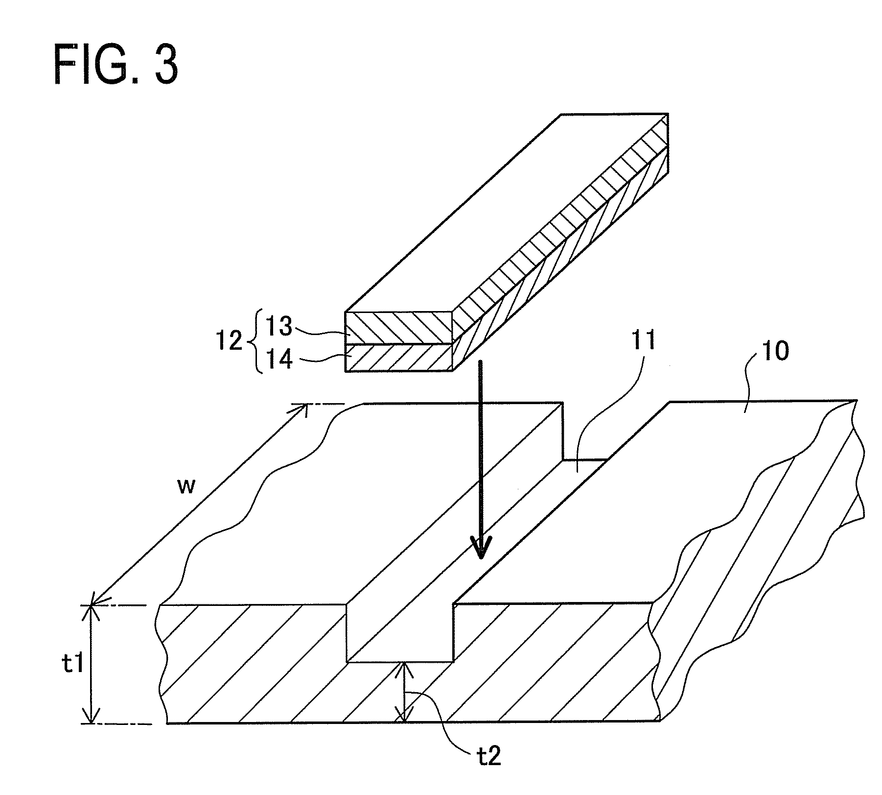
[0106]A second embodiment of the present invention will be explained below. As with the first embodiment, an electromagnetic steel sheet 10 constituting a rotor 90 is formed with a recess, and a two-layered chip 12 including a stainless steel foil 13 and a modifier metal foil 14 is set in the recess as shown in FIG. 3. Also, as with the first embodiment, a portion in which the two-layered chip 12 is set is sandwiched and applied with electric current as shown in FIG. 4 to melt the modifier metal foil 14 and the interior portions of the stainless steel foil 13 and of the electromagnetic steel sheet 10, that is, in the same process as shown in the upper view in FIG. 6 to the upper view in FIG. 8. A three-layer structure is also formed after the temperature falls down as with the first embodiment. In other words, an electromagnetic steel sheet layer 1, a stainless steel layer 3, and a solidified nonmagnetic alloy layer 2 are formed.

[0107]A difference from the first emb...

Example

[0110]A third embodiment of the invention will be explained below. A rotor 90 in this embodiment can rotate at high speed during use. At that time, a strong centrifugal force is exerted on an electromagnetic steel sheet 10 and a nonmagnetic portion X. Accordingly, it is necessary to ensure strength to withstand the centrifugal force. The rotor 90 is therefore desired to simultaneously have sufficient strength and prevent magnetic flux leakage in a nonmagnetic portion.

[0111]However, in a nonmagnetic alloy layer 2 and a stainless steel layer 3 to be formed after pressing and current applying, unjoined portions could be formed in a wall of a groove 11 as shown in FIG. 12. Specifically, unjoined portions 94 occur between the wall surfaces of the nonmagnetic alloy layer 2 and the stainless steel layer 3 and the electromagnetic steel sheet 10. When such unjoined portions 94 occur, stress resulting from the centrifugal force may concentrate on a slightly joined portion between the groove 1...


PUM

PropertyMeasurementUnit
Thicknessaaaaaaaaaa
Pressureaaaaaaaaaa
Heightaaaaaaaaaa

Abstract

Provided are a steel having a non-magnetic portion, which can be applied to the steel of the remaining portion irrespective of the material and which has a structure of a short treating time required and a determined depth direction, its manufacturing method, and a revolving electric core. There is prepared an electromagnetic steel sheet having a recessed groove. A two-layered chip of a modifier metal foil and a stainless steel foil is so set in the groove of the electromagnetic steel sheet that the electromagnetic steel sheet and the stainless steel foil have surfaces of the same height. The modifier metal foil is melted when electric current is applied under pressure. When this pressing and current applying is continued, inner sides of the electromagnetic steel sheet and the stainless steel foil contacting the modifier metal foil are melted to form a nonmagnetic alloy layer in the region excepting the surface portions of an electromagnetic steel sheet layer and a stainless steel layer. The nonmagnetic alloy layer and the stainless steel layer do not pass a magnetic flux.

Description

TECHNICAL FIELD[0001]The present invention relates to a steel suitable for use in a core of a revolving electric machine and the like and more particularly to a steel partly having a nonmagnetic portion, its producing method, and a revolving electric core.BACKGROUND ART[0002]A core for use in an electric motor, a power generator, and others is usually required to provide a high magnetic permeability. However, the core includes some portions that will not form any effective magnetic paths due to placement of coils and magnets. For instance, in a stator 80 and a rotor 90 as shown in FIG. 1, magnets 91 are mounted in the rotor 90. In this rotor 90, peripheral bridge portions 92 and central bridge portions 93 will not form paths of effective magnetic flux F. The presence of core material in such portions rather deteriorates the performance by leakage flux. It is therefore preferable to increase magnetic resistance in those portions. However, because of the need for maintaining the stren...

Claims


Application Information

Patent Timeline
IPC IPC(8): H01F21/06B32B15/01B23K31/02B32B15/18
CPCH02K1/02Y10T428/12965H02K15/03H02K1/2766
Inventor KADOTA, KEISUKEAIHARA, HIDEOMITSUBAYASHI, MASAHIKO
Owner TOYOTA JIDOSHA KK
Why Eureka
Try Eureka