[0020]In the method of fluoridation according to the aspect of the invention, the interior space structure that is reactive against
fluorine is exposed within the fluoridation treatment space, the fluoride layer is formed in advance on the surface of the interior space structure exposed within the fluoridation treatment space, and the fluoridation treatment if performed. Thus, the fluoride layer is formed on the surface of the interior space structure, therefore, a fluoridation source gas supplied for the fluoridation treatment of the workpiece is not excessively consumed for fluoridating the surface of the interior space structure during the fluoridation treatment. Further, even if a material and quantity of the workpiece are changed significantly depending on a lot and a situation where there is a deficiency of a fluoridation potential is caused, the fluoridation source gas is released from the fluoride layer on the surface of the interior space structure, and, therefore, the fluoride
atmosphere within the fluoridation treatment space is maintained properly during the fluoridation treatment. Therefore, a stable fluoridation quality can be obtained when performing the fluoridation treatment on various lots. Especially, further in a continuous
kiln which tends to have a shorter
treatment time, it is possible to achieve a treatment with a stable fluoridation quality. Further, even when a quantity of treatment of the workpiece having a strong oxide film, such as a stainless steel and the like, changes significantly, the oxide film is unfailingly removed and the fluoride layer can be formed with a targeted fluoridation quality. Therefore, a uniform treatment layer can be formed when, for example, performing a nitriding treatment or a low-temperature carburization treatment as a post-treatment. In the method of fluoridation according to the aspect of the invention, the fluoride layer formed on the surface of the interior space structure in advance may have the thickness of 1.3 μm or thicker in a portion where its fluorine concentration is 5
mass % or higher. Due to the fluoride layer being in a state where a growth rate is decreased because a
reaction rate control is finished and a
diffusion rate control is started, the fluoridation source gas can be less consumed by the surface of the interior space structure when the fluoridation treatment is performed afterwards. Further, because the above described fluoride layer holds a sufficient amount of fluorine, a sufficient amount of fluoridation source gas can be released when the potential of the fluoride atmosphere becomes low. Thus, even when fluoridation treatment is performed on various lots, a stable fluoridation quality can be obtained.
[0021]In the method of fluoridation according to the aspect of the invention, the fluoride layer formed at least in a section of the surface of interior space structure where its temperature becomes higher than the workpiece during the fluoridation treatment may have a thickness of 1.3 μm or thicker in a portion where its fluorine concentration is 5
mass % or higher. Thereby, it may further be beneficial to a stabilization of the fluoridation quality due to a stabilization of the fluoride atmosphere. That is, at the section where its temperature becomes higher than the workpiece, although a
fluoridation reaction consuming the fluoridation source gas in the fluoride atmosphere tends to proceed, a release of the fluoridation source gas due to a
decomposition of the fluoride layer when the potential of the fluoride atmosphere becomes low tends to occur. Therefore, by forming the fluoride layer in the section where the temperature becomes higher than the workpiece, the fluoridation source gas consumed by the surface of the interior space structure can be reduced, and the effect on stabilizing the fluoride atmosphere can be more noticeably obtained due to the fluoridation source gas being released when the potential of the fluoride atmosphere becomes low.
[0022]The unit of fluoridation according to the aspect of the invention is configured so that the fluoridation treatment is performed in the state where the interior space structure that is reactive against fluorine is exposed within the fluoridation treatment space, and the fluoride layer is formed in advance on the surface of the interior space structure exposed within the fluoridation treatment space. Thus, the fluoride layer is formed on the surface of the interior space structure in advance, therefore the fluoridation source gas supplied for the fluoridation treatment of the workpiece is not excessively consumed for fluoridating the surface of the interior space structure during the fluoridation treatment. Further, even if a material and quantity of the workpiece are changed significantly depending on a lot and causes a situation where there is a deficiency of a fluoridation potential of the supplied fluoridation source gas, the fluoridation source gas is released from the fluoride layer on the surface of the interior space structure, and, therefore, the fluoride atmosphere within the fluoridation treatment space is maintained properly during the fluoridation treatment. Thus a stable fluoridation quality can be obtained when performing the fluoridation treatment on various lots. Especially, further in a continuous
kiln which tends to have a shorter
treatment time, a treatment with a stable fluoridation quality can be achieved. Further, even when a quantity of treatment of the workpiece having a strong oxide film, such as a stainless steel, and the like changes significantly, the oxide film is unfailingly removed and the fluoride layer can be formed with a targeted fluoridation quality. Therefore, a uniform hardened layer can be formed when, for example, performing a nitriding treatment or a low-temperature carburization as a post-treatment.
[0023]The unit of fluoridation according to the aspect of the invention may further include a post-treatment space where the post-treatment is performed after the fluoridation treatment. The fluoridation treatment space may exist independently from the post-treatment space and may be provided with a transporting module for transporting the workpiece from the fluoridation treatment compartment to the post-treatment compartment. Therefore, the fluoridation source
gas consumption by the surface of the interior space structure may be suppressed, and also the stability of the fluoride atmosphere due to releasing of the fluoridation source gas when the potential of the fluoride atmosphere becomes low may not be affected and disturbed by the existence of the post-treatment space. Further, because the workpiece travels from the pre-heated fluoridation treatment compartment to the post-treatment compartment, the time required to raise the temperature of the workpiece in each treatment compartment can be reduced, and, in addition, a highly productive
mass production treatment with a stable post-
treatment quality can be performed even with a short
treatment time.
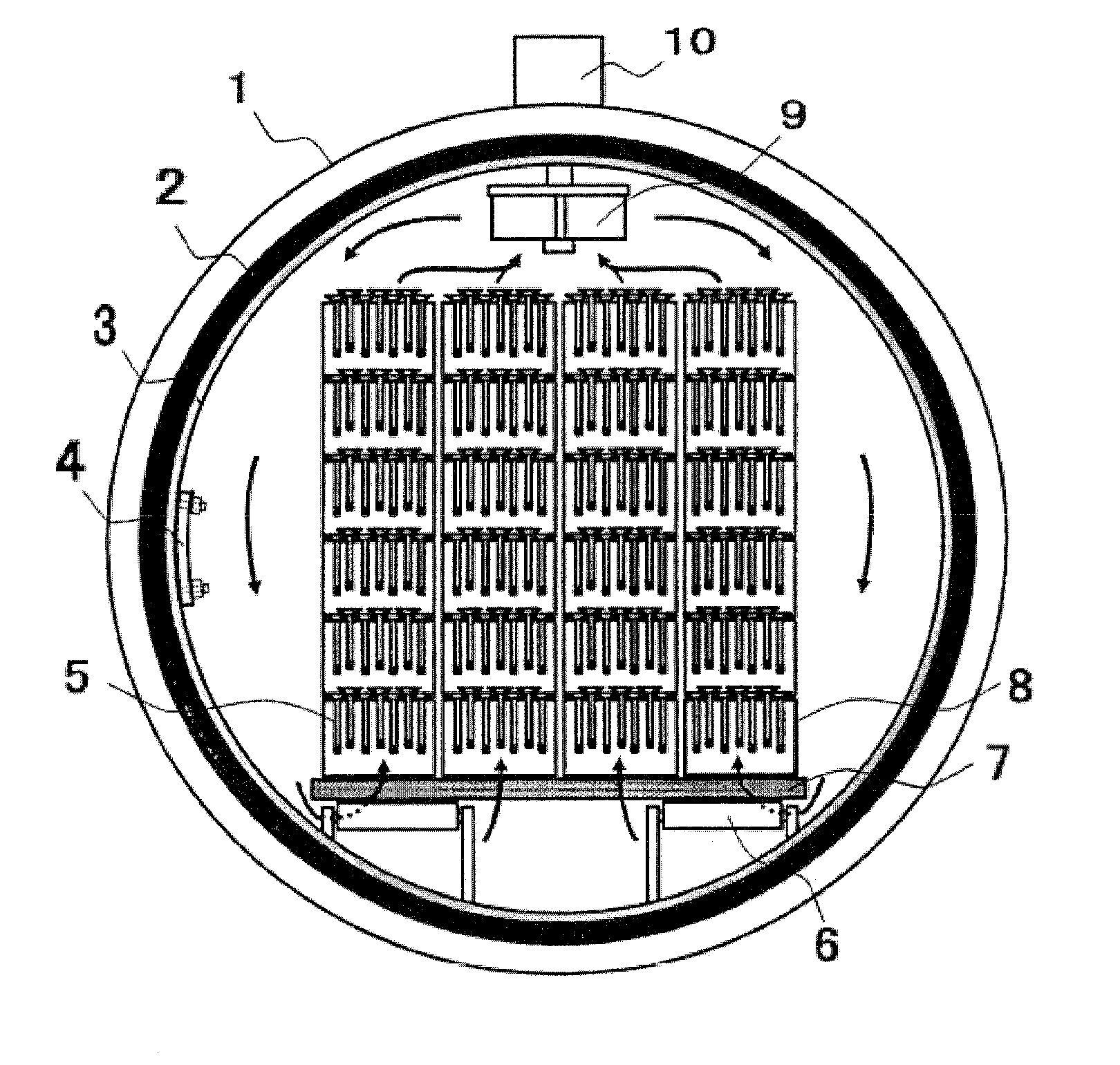
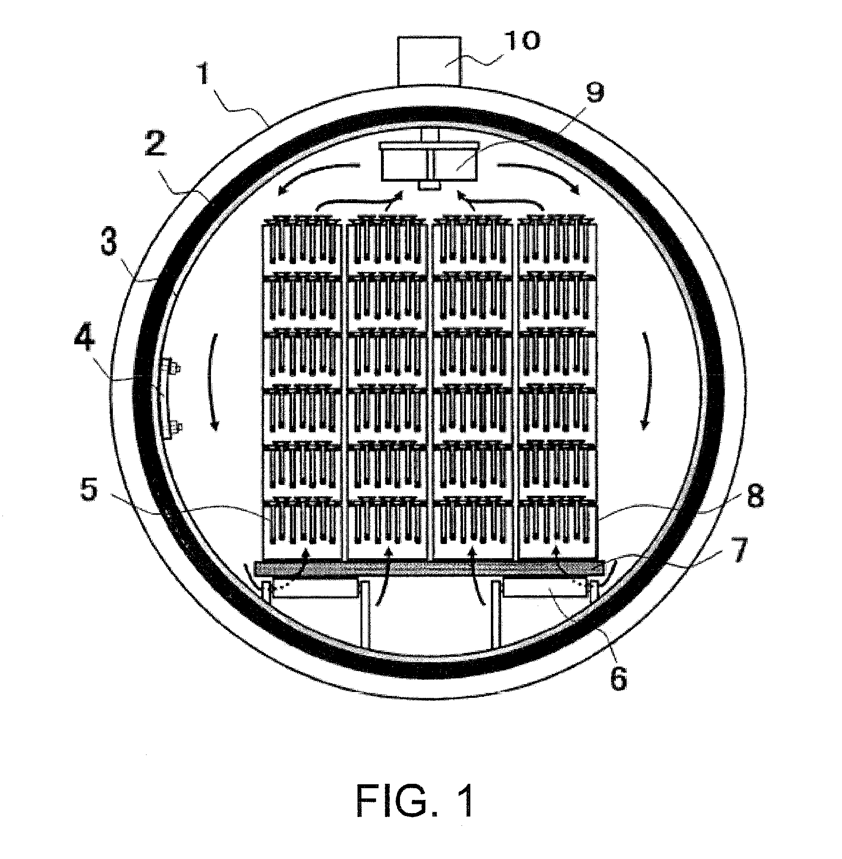
[0024]In the unit of fluoridation according to the aspect of the invention, the fluoridation treatment compartment may be formed in a cylindrical shape with its axis oriented along a transporting direction of the workpiece. Therefore, the fluoridation source gas may circulate well within the fluoridation treatment space, and the atmosphere gas circulating within the fluoridation treatment space may effectively prevent uneven distribution of the fluoridation source gas within the space even when a small amount of fluoridation source gas is consumed by the surface of the interior space structure. Further, the atmosphere gas circulating within the fluoridation treatment space may effectively prevent uneven distribution of the fluoridation source gas within the space when a potential of the fluoride atmosphere becomes low and the fluoridation source gas is released. Thereby the fluoride atmosphere within the fluoridation treatment space can be homogenized and an effect on stabilizing the fluoridation treatment condition can be more noticeably obtained. Further, a gas
convection flow which significantly affects the temperature variation within the fluoridation treatment space occurs distinctly smoothly, and a variation of a
gas concentration within the fluoridation treatment space becomes extremely small, thus, a variation of fluoridation quality at a location within the fluoridation treatment space can be significantly reduced.
[0025]In the directions for use of the unit of fluoridation according to the aspect of the invention, the unit of fluoridation performs the fluoridation treatment in the state where the interior space structure that is reactive against fluorine is exposed within the fluoridation treatment space and the fluoride layer is formed in advance on the surface of the interior space structure exposed within the fluoridation treatment space. Thus, the fluoride layer is formed on the surface of the interior space structure in advance, therefore the fluoridation source gas supplied for the fluoridation treatment of the workpiece is not excessively consumed for fluoridating the surfaces of the interior space structure during the fluoridation treatment. Further, even if a material and quantity of the workpiece are changed significantly depending on a lot and a situation where there is a deficiency of a fluoridation potential of the fluoridation source gas is caused, the fluoridation source gas is released from the fluoride layer on the surface of the interior space structure, and, therefore, the fluoride atmosphere within the fluoridation treatment space is maintained properly during the fluoridation treatment. Thus a stable fluoridation quality can be obtained when performing the fluoridation treatment on various lots. Especially, further in a continuous
kiln which tends to have a shorter treatment time, a treatment with a stable fluoridation quality can be achieved. Further, even when a quantity of treatment of the workpiece having a strong oxide film, such as a stainless steel, and the like changes significantly, the oxide film is unfailingly removed and the fluoridation layer can be formed with a targeted of fluoridation quality. Therefore, a uniform hardened layer can be formed when, for example, performing a nitriding treatment or a low-temperature carburization as a post-treatment.

