
Display device, electronic apparatus and driving code generating circuit

a technology of code generation circuit and display device, which is applied in the direction of electric digital data processing, instruments, computing, etc., can solve the problem that the capacity necessary for the storage circuit cannot be sufficiently reduced

Inactive Publication Date: 2010-09-09
SEIKO EPSON CORP
View PDF13 Cites 16 Cited by
  • Summary
  • Abstract
  • Description
  • Claims
  • Application Information

AI Technical Summary

Benefits of technology

The invention is about a display device that reduces the amount of data needed to compress a driving code. This is achieved by storing a predetermined code and an identifier of the code in a separate storage circuit, and using a compression code that includes a first portion designating the number of indication values and a second portion designating the identifier of the code for each gray scale. This reduces the capacity necessary for the compression code, and allows for the effective reduction of data amount. The invention also includes a developing unit that generates the driving code based on a continuous code and a predetermined code stored in the compression code storage unit. Overall, the invention improves the efficiency of data compression and reduces the amount of data needed to store the driving code.

Problems solved by technology

Therefore, a case may occur in which the capacity necessary for the storage circuit cannot be sufficiently reduced.

Method used


Image

  • Display device, electronic apparatus and driving code generating circuit
  • Display device, electronic apparatus and driving code generating circuit
  • Display device, electronic apparatus and driving code generating circuit

Examples


first embodiment

A: First Embodiment

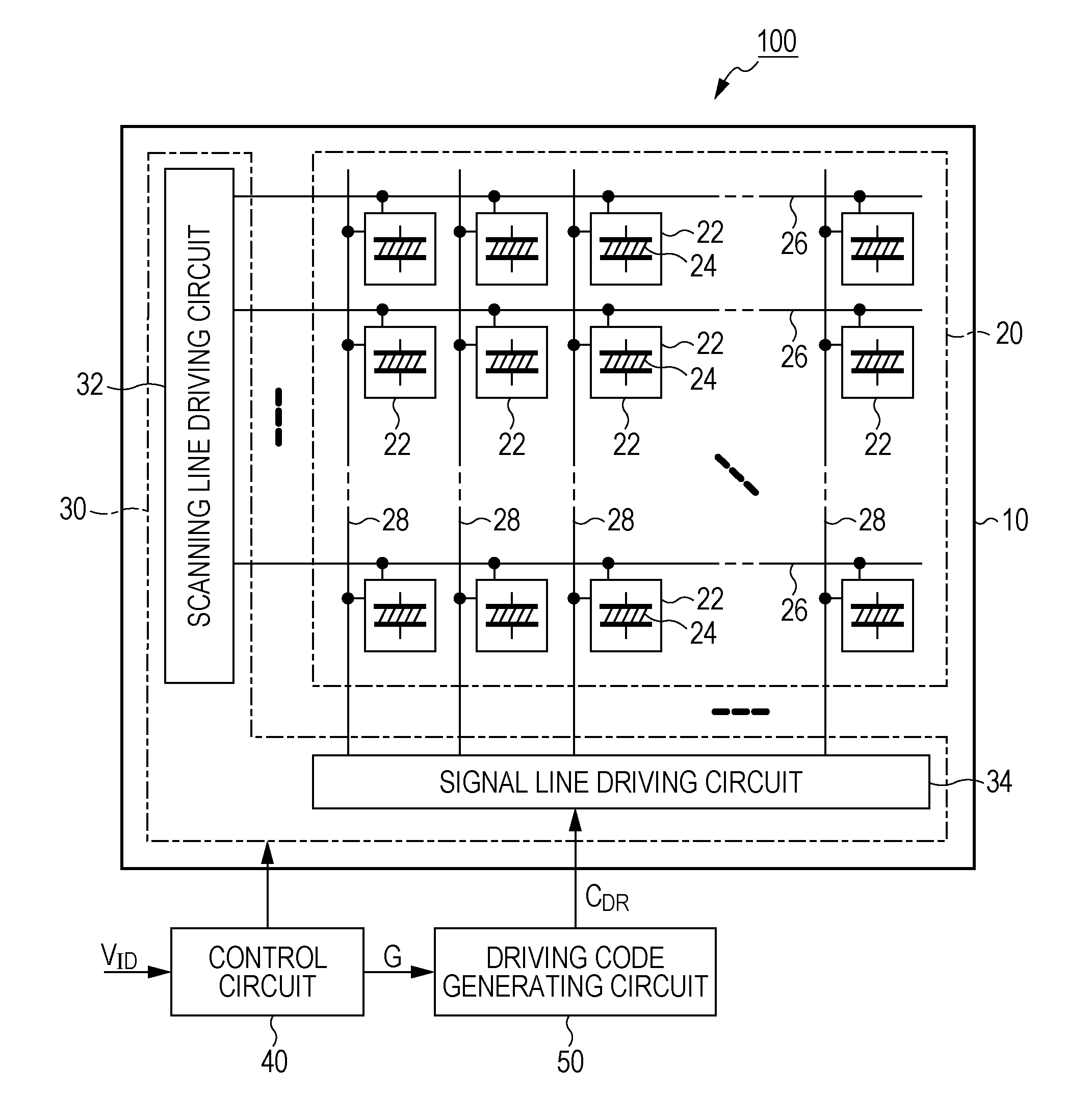
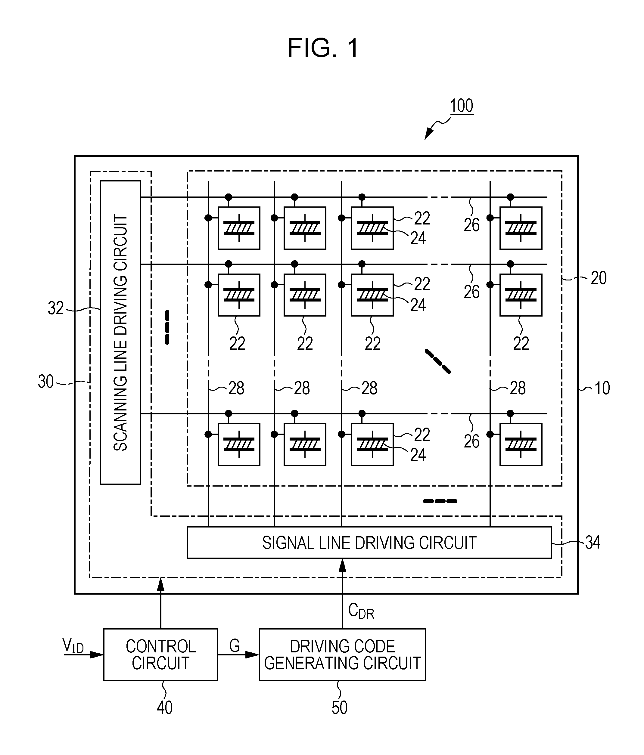
[0027]FIG. 1 is a block diagram illustrating a display device 100 according to a first embodiment of the invention. As illustrated in FIG. 1, the display device 100 includes a display panel 10, a control circuit 40 and a driving code generating circuit 50. The control circuit 40 and the driving code generating circuit 50, for example, are mounted on the surface of a board constituting the display panel 10, or the surface of a wiring board bonded to a liquid crystal panel. In addition, the control circuit 40 and the driving code generating circuit 50 can be prepared in the form of a single integrated circuit.

[0028]The display panel 10 includes a pixel unit (display area) 20 in which a plurality of pixel circuits 22 are arranged, and a driving circuit 30 that drives each pixel circuit 22. In the pixel unit 20, M scanning lines 26 and N signal lines 28 extend in the direction in which they cross each other (M and N are natural numbers). The pixel circuits 22 are each...

second embodiment

B: Second Embodiment

[0060]Next, the second embodiment of the invention will be descried. In the first embodiment, the developing unit 76 sequentially develops the gray scale data G, which is output from the control circuit 40 during the operation of the display panel 10, to the driving code CDR. In the second embodiment, the driving code CDR of each gray scale is developed before the display panel 10 starts to operate (e.g., immediately after the display device 100 is powered on). In addition, in the following embodiment, modified examples and application, the same reference numerals are used to designate elements having operations and functions identical to those of the first embodiment, and detailed description thereof will be omitted in order to avoid redundancy.

[0061]The second embodiment employs a driving code generating circuit 70 of FIG. 8, instead of the driving code generating circuit 50 according to the first embodiment. As illustrated in FIG. 8, a temperature detecting me...

first modified example

1 First Modified Example

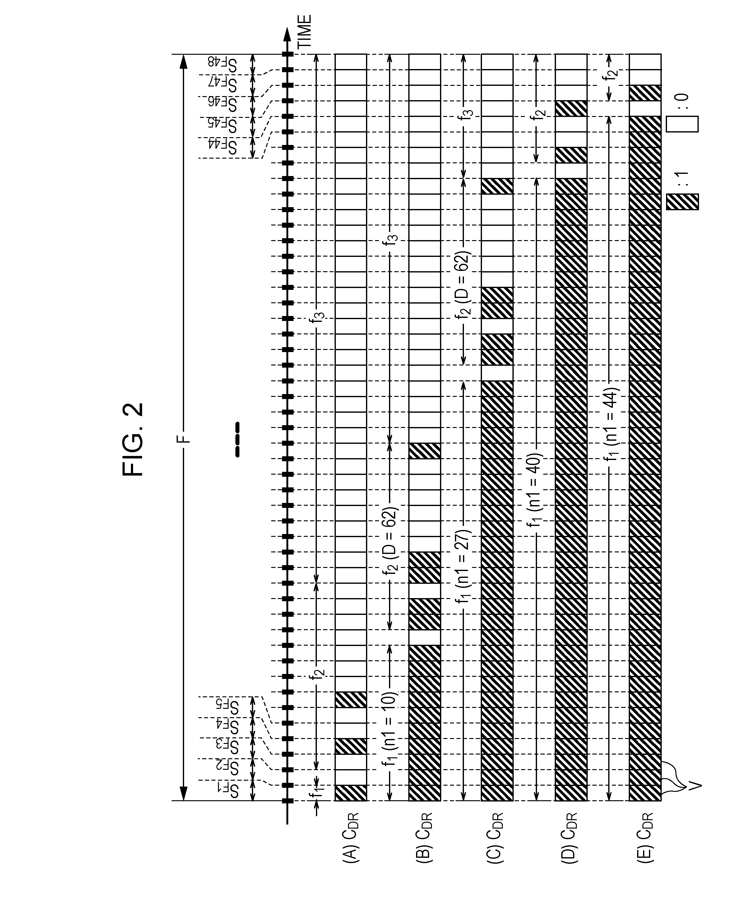
[0068]The order (in addition, order of the sequence code CA and the predetermined code CB) of the first section f1, the second section f2 and the third section f3 according to the previous embodiments may be appropriately changed. For example, it may be possible to employ a configuration in which the third section f3 is located prior to the second section f2 and the second section f2 is located prior to the first section f1. The developing units 54 and 76 add the indication value X of “0” corresponding to the boundary subfield SF just prior to the sequence code CA, connect the predetermined code CB just prior to the indication value X, and add the indication value X (indication value X corresponding to the third section f3) of “0” just prior to the predetermined code CB, thereby generating the driving codes CDR including 48 indication values X. Further, in the configuration in which the third section f3 is interposed between the first section f1 and the secon...


PUM


Abstract

A display device displays a gray scale by applying a voltage to a display element for each of a plurality of subfields. The display device includes a predetermined code storage unit that stores a predetermined code, in which indication values designating the voltage are arranged, a compression code storage unit that stores a compression code, which includes a first portion designating a number of the indication values and a second portion designating an identifier of the predetermined code, and a developing unit that generates a driving code according to a continuous code, in which indication values designating a first voltage are arranged by the number of the indication values designated by the first portion of the compression code, and a predetermined code corresponding to the identifier designated by the second portion of the compression code.

Description

BACKGROUND[0001]1. Technical Field[0002]The present invention relates to a technology capable of displaying gray scale by using a subfield driving scheme.[0003]2. Related Art[0004]According to the related art, there has been proposed a subfield driving scheme in which an on voltage or an off voltage is selectively applied to a display element (e.g., liquid crystal element) in each of a plurality of subfields obtained by dividing a field (for example, see JP-A-2003-114661). Further, JP-A-2008-241975 discloses a technology of storing a code (hereinafter, referred to as “driving code”), which indicate an on voltage or an off voltage in each subfield, in a storage circuit for each gray scale in a state in which the codes have been compressed.[0005]The code (hereinafter, referred to as “compression code”) after compression in JP-A-2008-241975 includes a first portion, which designates the number of subfields in which an on voltage is applied and being continuous in a field, and a second ...

Claims


Application Information

Patent Timeline
Patent Type & Authority Applications(United States)
IPC IPC(8): G09G5/10G09G3/34
CPCG09G3/2025G09G3/2029G09G2320/041G09G3/3648
Inventor TAKAHASHI, NARIYA
Owner SEIKO EPSON CORP
Learn More