
Liquid ejecting apparatus and liquid housing container

a technology of liquid ejecting apparatus and liquid housing container, which is applied in printing and other directions, can solve the problems of defective contact between terminals due to grinding power, insufficient consideration of suppression of grinding power generation, and high cost of reducing power generation, so as to suppress defective contact and suppress grinding powder generation

Inactive Publication Date: 2010-09-09
SEIKO EPSON CORP
View PDF5 Cites 55 Cited by
  • Summary
  • Abstract
  • Description
  • Claims
  • Application Information

AI Technical Summary

Benefits of technology

[0008]An advantage of some aspects of the invention is that it provides technology for suppressing occurrence of defective contact between terminals by suppressing generation of grinding powders due to grind of a liquid housing container.
[0013]According to the liquid ejecting apparatus of Application 2, the first terminal is not brought into contact with anything but the second terminal. Accordingly, defective connection between terminals can be suppressed by suppressing generation of grinding powders further.

Problems solved by technology

As a result, there is a problem that defective contact between terminals due to the grinding powers occurs.
However, in such typical technology, suppression of generation of grinding powers has not been sufficiently considered.
Furthermore, decreasing the generation of the powers is demanding.
In addition, such a problem is not limited to relationship between a printing apparatus and an ink cartridge and, generally, is a problem common to relationship between a liquid ejecting apparatus main body and a liquid housing container having a terminal for communicating with the liquid ejecting apparatus.

Method used


Image

  • Liquid ejecting apparatus and liquid housing container
  • Liquid ejecting apparatus and liquid housing container
  • Liquid ejecting apparatus and liquid housing container

Examples


first embodiment

A. First Embodiment

B: Second Embodiment

C: Third Embodiment

D: Modified Examples

A. First Embodiment

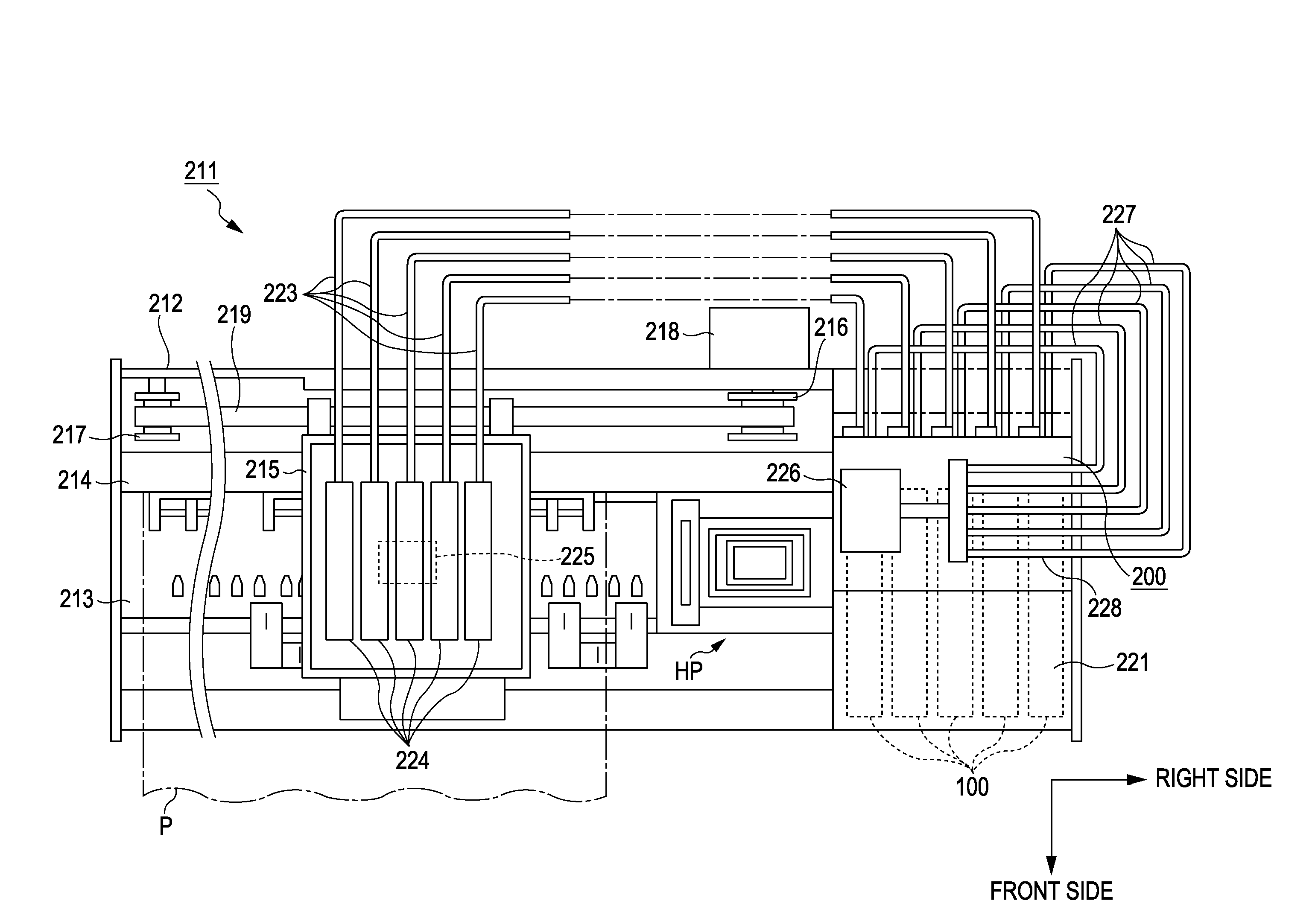
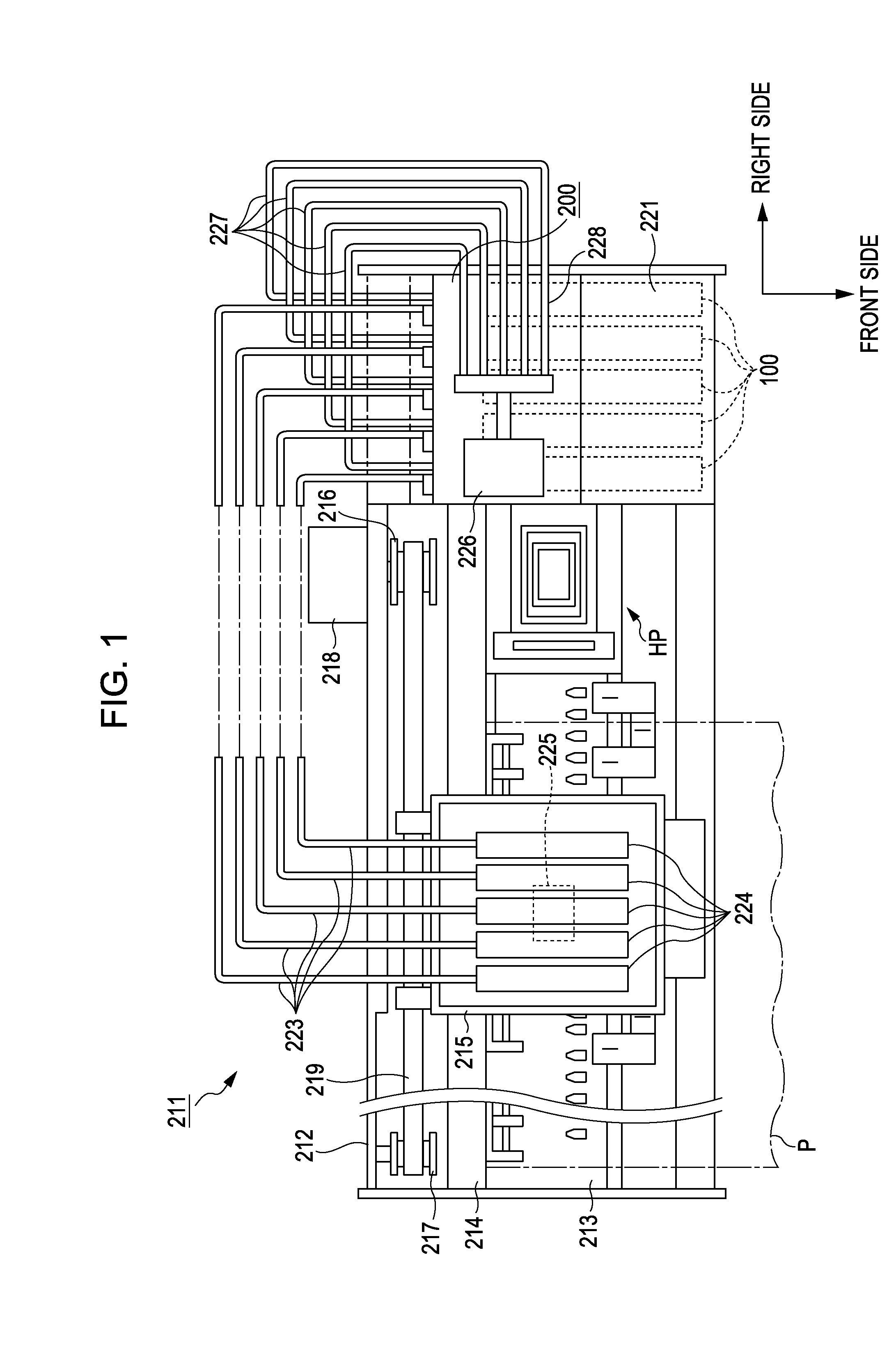
[0044]FIG. 1 is a schematic diagram showing the configuration of a liquid ejecting apparatus according to an embodiment of the invention. An ink jet printing apparatus 211 as a liquid ejecting apparatus according to this embodiment, as shown in FIG. 1, includes a main body case 212 having an approximately rectangular box shape. In the lower part inside the main body case 212 on the front side, a platen 213 is disposed along the longitudinal direction (the horizontal direction in FIG. 1), which is the main scanning direction, of the main body case 212. The platen 213 is a support board that supports a printing sheet P as a target. On the platen 213, a printing sheet P is transported in the sub scanning direction perpendicular to the main scanning direction by a paper transport mechanism not shown in the figure.

[0045]Inside the main body case 212, above the rear portion of the platen 213, ...

second embodiment

B. Second Embodiment

[0158]FIGS. 20 to 23 are explanatory diagrams schematically showing the procedure of inserting an ink cartridge 100b into a cartridge holder 200b according to a second embodiment of the invention. The difference from the first embodiment shown in FIGS. 16 to 19 is that any inclination portion is not disposed in the position determining holes 21 and 23, and an inclination portion 247a is disposed in a position determining pin 247b, and other configurations are the same as those of the first embodiment. As described above, even when the inclination portion 247a is disposed in the position determining pin 247b, as in the first embodiment, generation of grinding powers of the surface 15 of the ink cartridge 100 or the cocking pin 18 is suppressed. Accordingly, occurrence of defective contact between terminals can be suppressed.

third embodiment

C. Third Embodiment

[0159]FIGS. 24A and 24B are explanatory diagrams schematically showing the procedure of inserting an ink cartridge 100c into a cartridge holder 200c according to a third embodiment of the invention. FIGS. 24A and 24B are plan views of the ink cartridge 100c, viewed from a first side face 15 (top face). FIG. 24A shows a state in the middle of inserting the ink cartridge 100c. FIG. 24B shows a state in which the ink cartridge 100c is completely inserted into the cartridge holder 200c. The differences from the first embodiment shown in FIGS. 16 to 19 are as follows.

[0160]The circuit substrate 17 is disposed on a side face 35a (third side face 35a) of the ink cartridge 100c.

[0161]Partition Walls 300 and 301 are disposed.

[0162]A device-side terminal 250c is disposed on the partition wall 300.

[0163]Any inclination portion is not disposed in position determining holes 21 and 23, and an inclination portion 247a is disposed in a position determining pin 247c.

[0164]A regu...


PUM


Abstract

A liquid ejecting apparatus includes a liquid housing container that is housed by a container housing portion. The container housing portion includes a first terminal connecting to the liquid housing container. A position determining pin defines an insertion direction in which the liquid housing container is inserted into the container housing portion. The liquid housing container includes a circuit substrate and a second terminal connecting to the first terminal. A position determining hole determines the position of the liquid housing container by inserting the position determining pin therein. An inclination portion is configured such that the first terminal first contacts a member disposed on a substrate mounting face, on which the circuit substrate is installed, of faces of the liquid housing container, by inserting the position determining pin into the position determining hole along the inclination portion when the liquid housing container is inserted into the container housing portion.

Description

BACKGROUND[0001]1. Technical Field[0002]The present invention relates to a liquid ejecting apparatus and a liquid housing container.[0003]2. Related Art[0004]In an ink jet printing apparatus as an example of a liquid ejecting apparatus, typically, an ink cartridge that is a detachable liquid housing container is installed. There are ink cartridges in which a circuit substrate having a memory element is mounted. In the memory element, for example, various types of information such as the amount of ink inside the ink cartridge and the colors of ink are stored. By connecting a terminal disposed on the circuit substrate of the ink cartridge and a terminal disposed on a main body side of the printing apparatus to each other, the printing apparatus reads or writes (access) information stored in the memory element of the ink cartridge.[0005]Generally, when an ink cartridge is inserted into a cartridge holder (container housing portion) of the printing apparatus, the terminal disposed on th...

Claims


Application Information

Patent Timeline
IPC IPC(8): B41J2/14
CPCB41J2/17526B41J2/1752
Inventor AOKI, YUJIKIMURA, HITOTOSHI
Owner SEIKO EPSON CORP
Learn More