Susperconductive Multi-Phase Cable System, a Method of Its Manufacture and Its Use

a multi-phase, fluid-cooled cable technology, applied in the direction of superconducting magnets/coils, superconductor devices, magnetic bodies, etc., can solve the problems of large materials use, low efficiency during use, complex and time-consuming manufacturing process of fluid-cooled cable systems, etc., to achieve flexible and efficient use

Active Publication Date: 2010-09-09
NKT CABLES ULTERA
View PDF4 Cites 25 Cited by
  • Summary
  • Abstract
  • Description
  • Claims
  • Application Information

AI Technical Summary

Benefits of technology

[0147]In a particular embodiment, the multiphase cable system can be used as both an AC-cable system or a DC cable system without any change at all of the cable design. This has the advantage of rational production, i.e. no change of any parameters for two different orders. It also has the advantage of enabling an AC to DC switchover by the electrical system operator, after the superconducting power line ha

Problems solved by technology

A problem of the prior art is that the manufacturing process for a fluid cooled cable system is

Method used


Image

  • Susperconductive Multi-Phase Cable System, a Method of Its Manufacture and Its Use
  • Susperconductive Multi-Phase Cable System, a Method of Its Manufacture and Its Use
  • Susperconductive Multi-Phase Cable System, a Method of Its Manufacture and Its Use

Examples


example 1

A DC cable

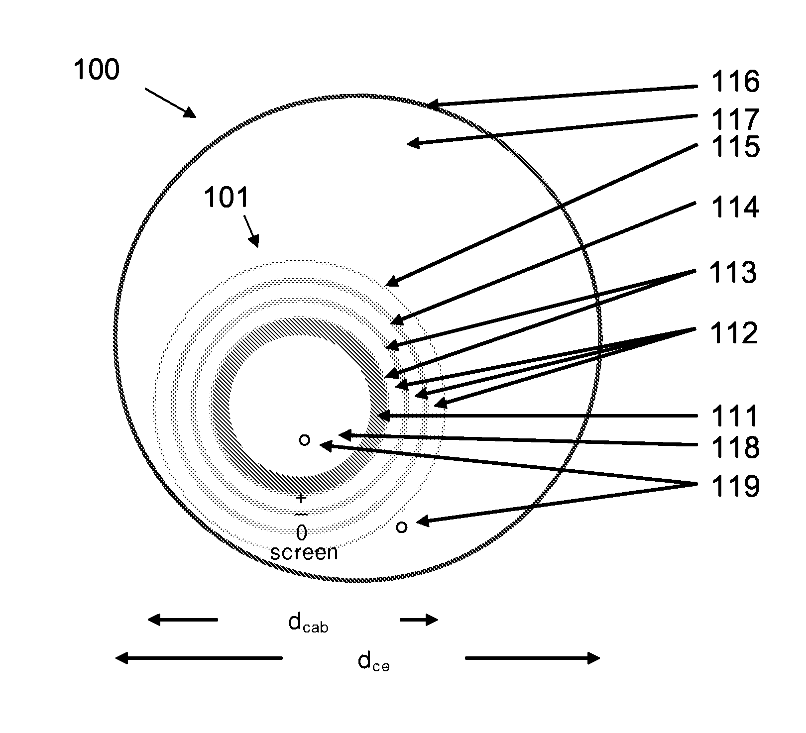
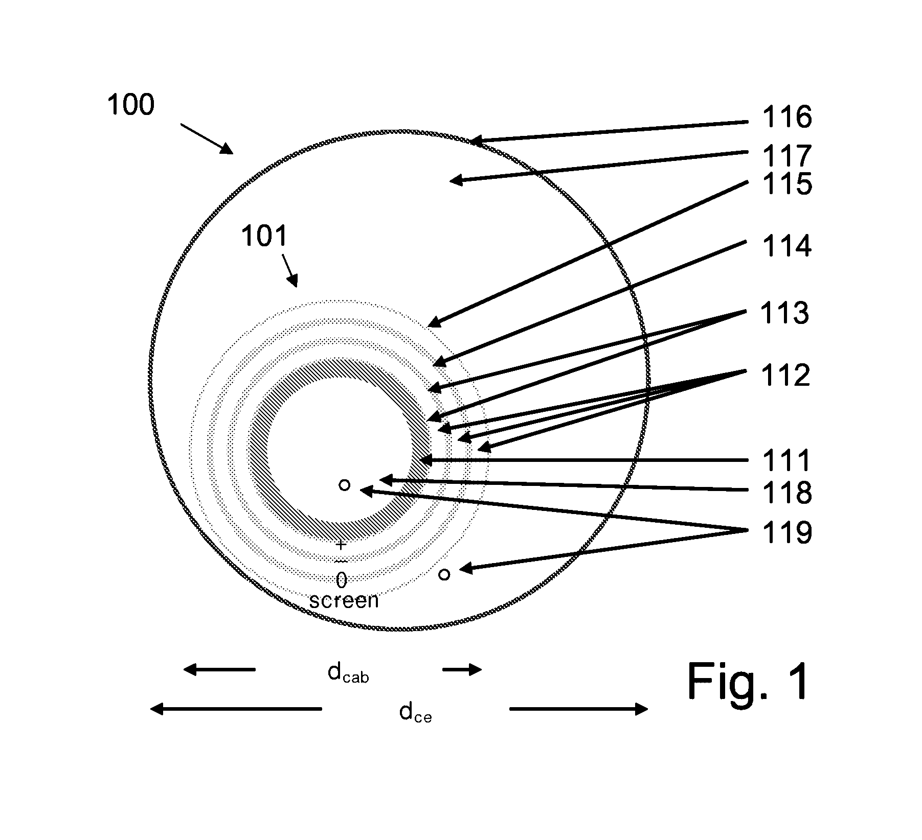
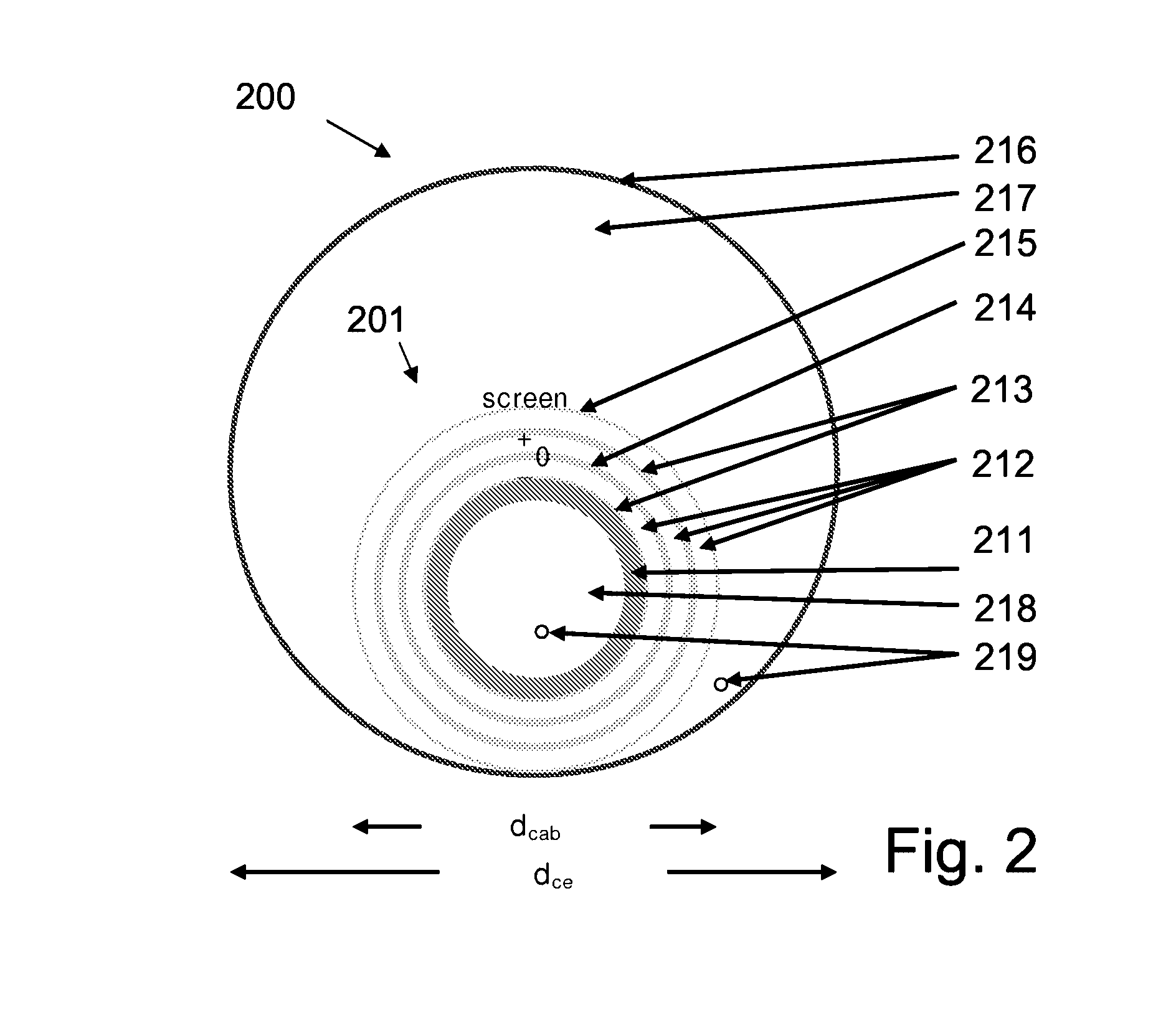
[0164]Preferred embodiments of a triaxial DC cable system are shown in FIG. 1 and FIG. 2. FIG. 1 shows a cross-sectional view of triaxial DC cable system according to the invention in a [+, −, 0, screen]-configuration whereas FIG. 2 shows a cross-sectional view of triaxial DC cable system according to the invention in a [−, 0, +, screen]-configuration. FIG. 3 shows a detailed cross-sectional view of the layers of the cable for the triaxial DC cable system of FIG. 2.

[0165]The two examples represent similar cable builds but with the poles, +, −, 0 plus screen differently arranged. Another possible build is to have only +, 0, screen or +, −, screen in combination with neutral. Yet other combinations can be envisioned having even more poles with different DC voltages, e.g. ±10 kV, ±20 kV, ±30 kV, 0 and screen.

[0166]In the embodiments shown, the outer cross-sectional diameter of the cable (dcab in FIG. 1 and FIG. 2) is 70 mm (2.75″) and the inner cross-sectional diameter of the...

example 2

An AC Cable

[0188]Preferred embodiments of a three-phase AC cable system are shown in FIG. 4 and FIG. 5. FIG. 4 shows a cross-sectional view of triaxial AC cable system according to the invention in a [R, T, S, screen]-configuration. FIG. 5 shows a cross-sectional view of triaxial AC cable system according to the invention in a [R, S, T, screen]-configuration. FIG. 6 shows a detailed cross-sectional view of the layers of the cable for the triaxial AC cable system of FIG. 5.

[0189]In the following reference is made to FIG. 4, FIG. 5 and FIG. 6, quoting reference numerals “4xy; 5xy” from FIG. 4 and FIG. 5, respectively (4xy referring to details on FIGS. 4 and 5xy referring to equivalent details on FIG. 5, FIG. 6 being a detailed view of parts of FIG. 5 and hence comprising reference numerals 5xy).

[0190]The two examples of FIG. 4 and FIG. 5 represent similar cable builds but with the phases differently permuted R, S, T and R, T, S, respectively.

[0191]The cable 401; 501 consists of a mult...


PUM

PropertyMeasurementUnit
Fractionaaaaaaaaaa
Pressureaaaaaaaaaa
Lengthaaaaaaaaaa

Abstract

The invention relates to a superconductive multi-phase, fluid-cooled cable system comprising a) a cable comprising at least three electrical conductors constituting at least two electrical phases and a zero- or neutral conductor, said electrical conductors being mutually electrically insulated from each other, and b) a thermal insulation defining a central longitudinal axis and having an inner surface and surrounding the cable, said inner surface of said thermal insulation forming the radial limitation of a cooling chamber for holding a cooling fluid for cooling said electrical conductors. The invention further relates to a method of manufacturing a cable system and to its use. The object of the present invention is to provide a simplified manufacturing and installation scheme for a fluid cooled cable system. The problem is solved in that said cable—at least over a part of its length—is located eccentrically relative to said central longitudinal axis when viewed in a cross section perpendicular to said longitudinal axis and where the eccentric location has the function of accommodating thermal shrinkage and expansion of the cable with respect to the thermal insulation.

Description

TECHNICAL FIELD[0001]The present invention relates to AC or DC cables for power distribution.[0002]The invention relates specifically to a superconductive multi-phase, fluid-cooled cable system. The invention furthermore relates to a method of manufacturing a cable system and to its use.[0003]The invention may e.g. be useful in applications such as low, medium and high-voltage superconductive cables for power distribution.BACKGROUND ARTTriax[0004][G. Bogner, Transmission of electrical energy by superconducting cables, in “Superconducting Machines and Devices”, Ed. S. Foner and B. Schwartz (Plenum Publishing Co., 1974), pp. 430-431] and [T. Tanaka, A. Greenwood, Advanced Power Cable Technology—Volume II: Present and Future, (1983, CRC Press, Boca Raton, Fla.), pp. 242-259] describe a triaxial superconducting cable with three concentric phase conductors. The superconductors are applied to the surfaces of cooling ducts suspended in vacuum. The middle conductor is described as a double ...

Claims


Application Information

Patent Timeline
IPC IPC(8): H01L39/04H01B12/10H01L39/24H01B12/16
CPCH01B12/16Y10T29/49014H01B12/14Y02E40/647Y02E40/60H01B12/00
Inventor WILLEN, DAGTRAEHOLT, CHRESTENDAUMLING, MANFREDTOLBERT, JERRY C.RODEN, MARKLINDSAY, DAVID
Owner NKT CABLES ULTERA
Why Eureka
Try Eureka