Sensor guide wire with micro-cable winding

a technology of micro-cables and sensors, applied in the direction of guide wires, micro-scale sensors, medical science, etc., can solve the problems of rotational whipping, difficulty in pushing the sensor guide forward into the vessel,

Active Publication Date: 2010-09-09
ST JUDE MEDICAL COORDINATION CENT
View PDF36 Cites 69 Cited by
  • Summary
  • Abstract
  • Description
  • Claims
  • Application Information

AI Technical Summary

Problems solved by technology

It should, however, also be recognized that if the core wire is too flexible, it would be difficult to push the sensor guide forward into the vessels, i.e. the sensor guide must possess a certain “pushability”.
One drawback with this design is that the guide wire when rotated has a tendency to store the elastic energy or the built up torque and release it, resulting in a rotational whipping.

Method used


Image

  • Sensor guide wire with micro-cable winding
  • Sensor guide wire with micro-cable winding
  • Sensor guide wire with micro-cable winding

Examples


Embodiment Construction

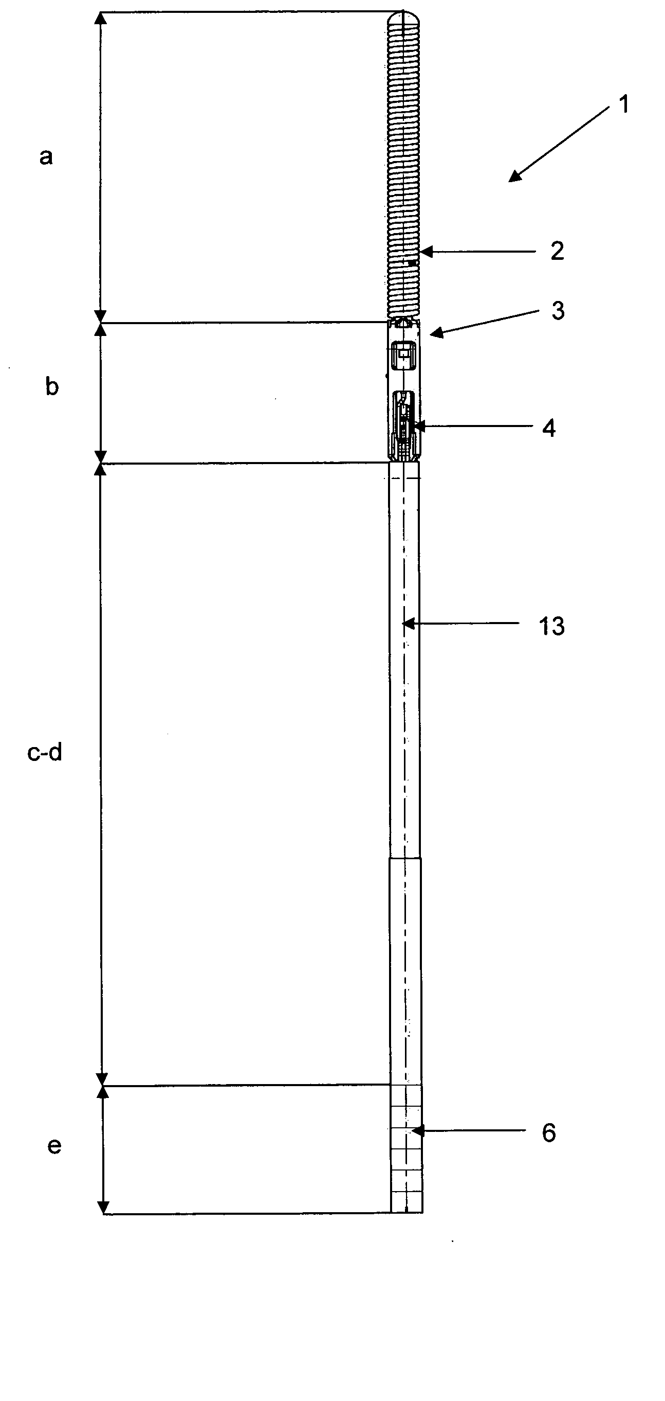
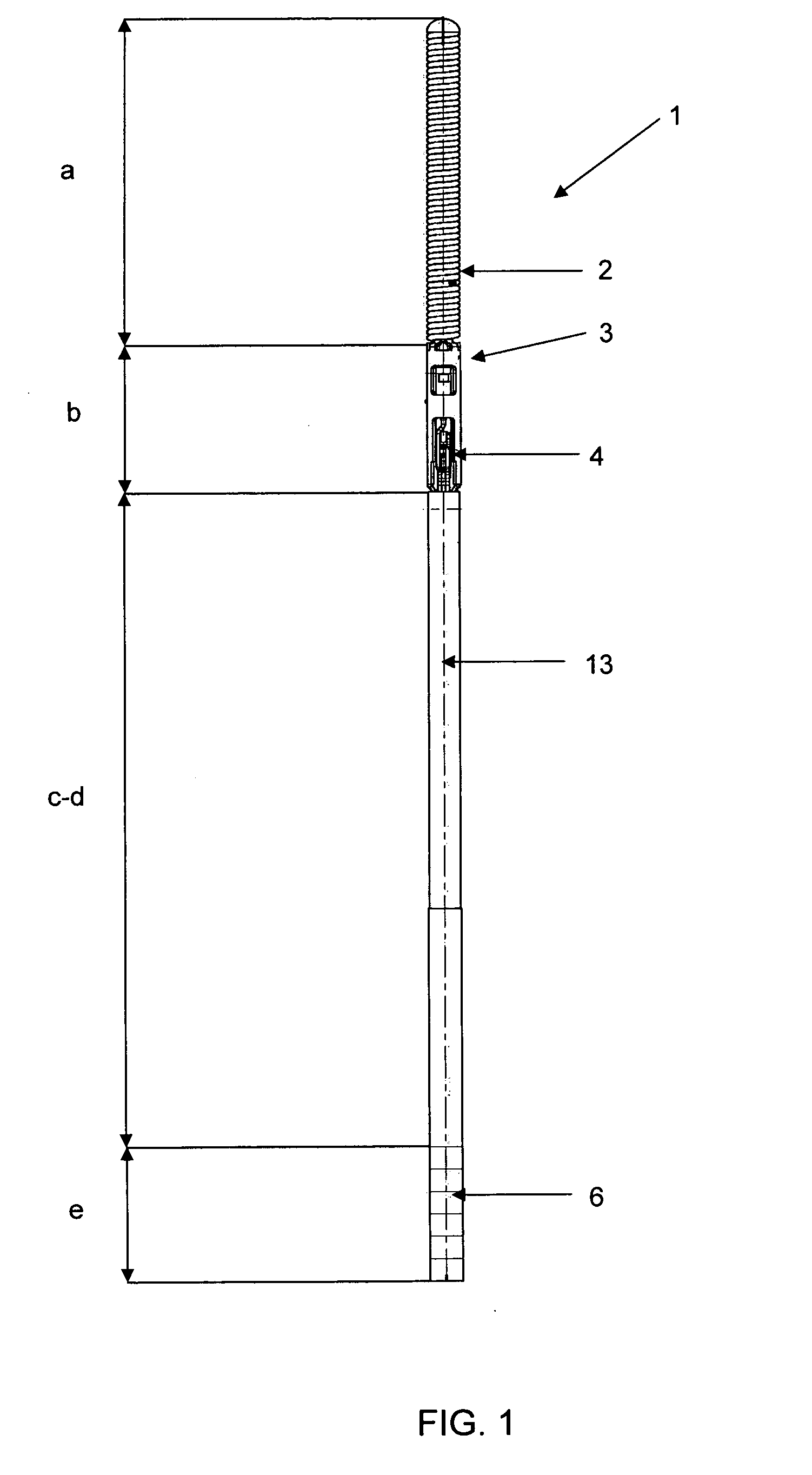
[0024]With reference to FIG. 1, a sensor guide wire 1 e.g. as exemplified by the above-mentioned EP-1 475 036 is shown. The guide wire 1 has been divided in different regions, a-e, where region a is the most distal region and e is the most proximal region. The different regions are: a) Tip region, b) Sensor region, c) Flexible region, d) Shaft region, and e) Male connector region. In an exemplary embodiment, region a) is about 10-50 mm, region b) is about 1-5 mm, region c) is about 150-400 mm, region d) is about 1000-2000 mm and region e) is about 10-100 mm. The diameter of the sensor guide wire 1 preferably varies between 0.25-2.5 mm; for use in coronary arteries, the diameter is normally 0.35 mm.

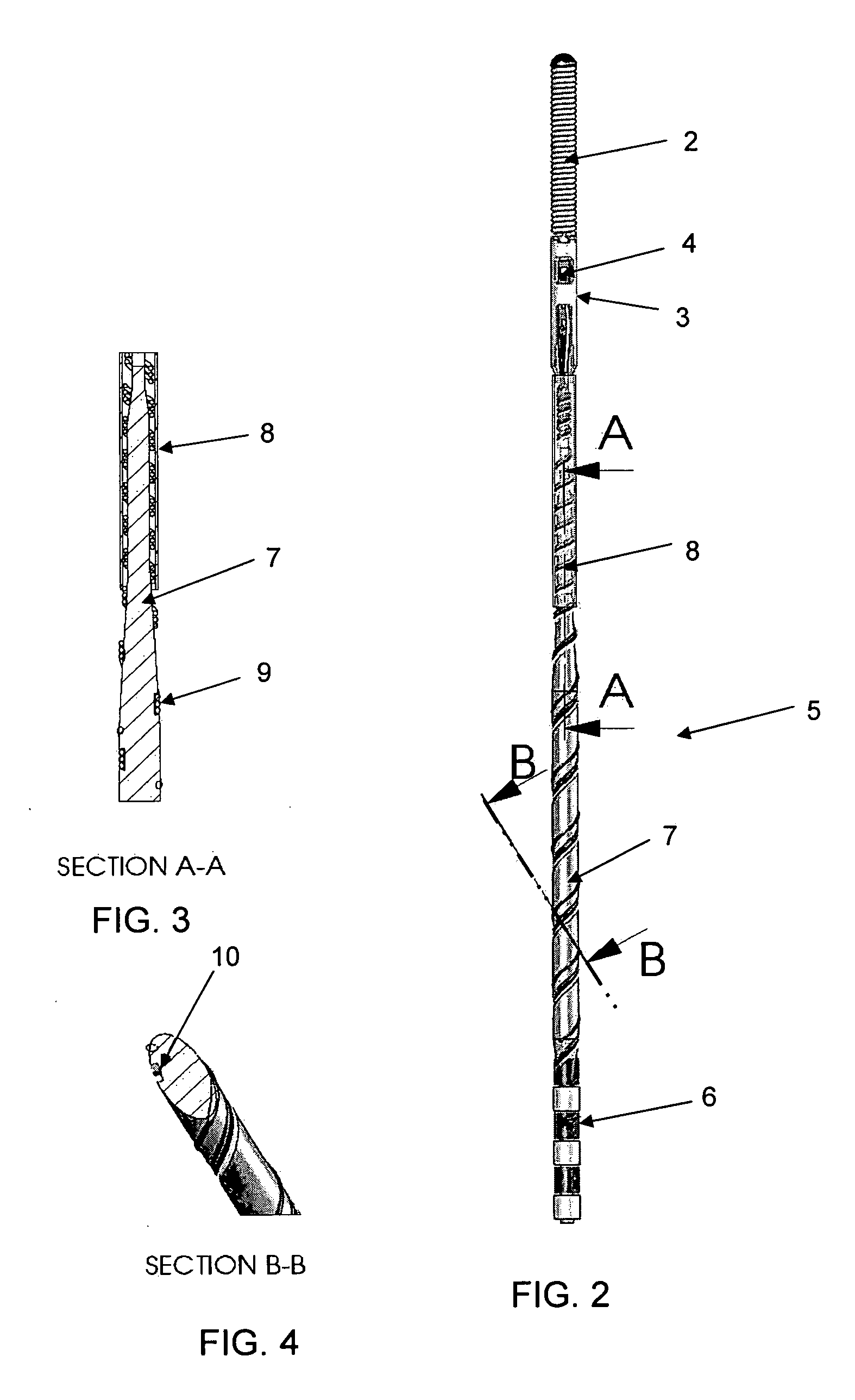
[0025]The tip region includes a radioopaque tip 2, in this embodiment in the shape of a coil. The tip region bridges to the sensor region, which includes a sensor element 4 accommodated in a jacket 3. In order to power the sensor element 4 and to communicate signals representing the measur...


PUM


Abstract

Sensor guide wire for intravascular measurements of a physiological variable in a living body, comprising: a sensor region in a distal part of the sensor guide wire, a sensor element arranged in the sensor region, a male connector at a proximal part of the sensor guide wire, a least one electrical micro-cable connecting the male connector to the sensor element and an elongated guide wire body arranged between the sensor region and the male connector. The at least one electrical micro-cable extends essentially helically around the guide wire body along the length of at least a part of the guide wire.

Description

FIELD OF THE INVENTION[0001]The present invention relates to a sensor guide wire for intravascular measurements of a physiological variable in a living body according to the preamble of the independent claim.BACKGROUND OF THE INVENTION[0002]In many medical procedures, various physiological conditions present within a body cavity need to be monitored. These physiological conditions are typically physical in nature—such as pressure, temperature, rate-of-fluid flow, and provide the physician or medical technician with critical information as to the status of a patient's condition.[0003]One device that is widely used to monitor conditions is the blood pressure sensor. The sensor is typically included in a guide wire for intravascular measurements. A blood pressure sensor senses the magnitude of a patient's blood pressure, and converts it into a representative electrical signal that is transmitted to the exterior of the patient. For most applications it is also required that the sensor i...

Claims


Application Information

Patent Timeline
Patent Type & Authority Applications(United States)
IPC IPC(8): A61B5/04
CPCA61B5/0215A61B5/6851A61B2017/22038A61M2025/09183A61M25/09A61M2025/09133A61B2562/028
Inventor VON MALMBORG, PAR
Owner ST JUDE MEDICAL COORDINATION CENT
Why Eureka
Try Eureka