Cleated athletic shoe with cushion structures

Active Publication Date: 2010-09-16
UNDER ARMOUR
View PDF13 Cites 88 Cited by
  • Summary
  • Abstract
  • Description
  • Claims
  • Application Information

AI Technical Summary

Benefits of technology

[0007]One aspect of the present invention is to address and resolve the above-noted limitations with conventional footwear wherein the integrati

Problems solved by technology

Specifically, the weight, cushioning, and lateral stability characteristics of a shoe can be a strong determinant of performance because they may directly impact an athlete's speed, endurance, and sure-footing.
Yet these efforts have produced overly stiff shoes, shoes with inadequate lateral stability, or unnecessarily heavy shoes not meeting the requirements of serious athletes and active athletic participants.
Although foregoing efforts have been met with varying degrees of success, there remains an unresolved need for cleated athletic

Method used


Image

  • Cleated athletic shoe with cushion structures
  • Cleated athletic shoe with cushion structures
  • Cleated athletic shoe with cushion structures

Examples


first embodiment

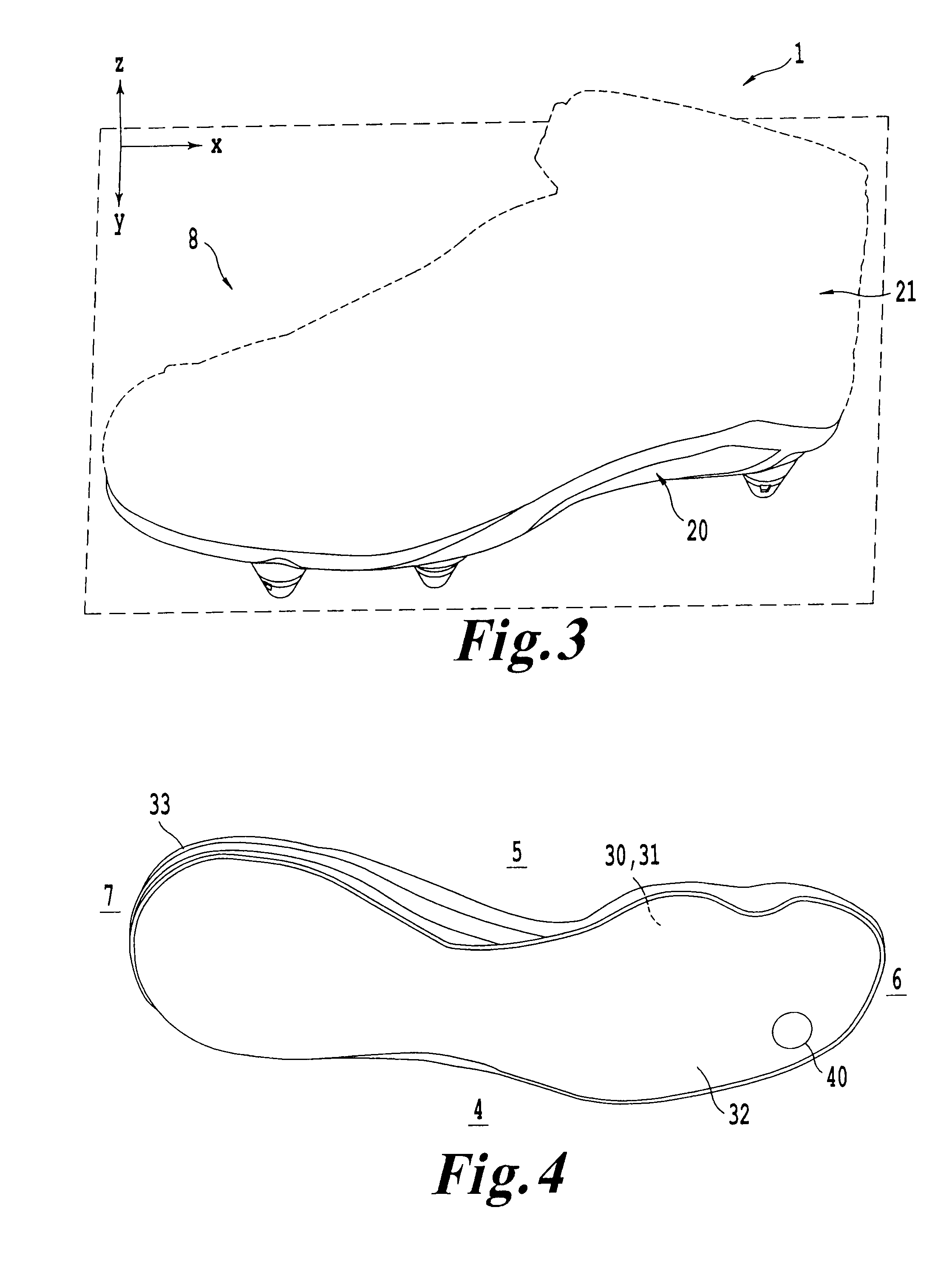
[0039]FIG. 4 shows a primary midsole 30 consistent with the present invention. The primary midsole 30 may comprise a top midsole surface 31, a bottom midsole surface 32 and a midsole periphery edge 33. The primary midsole 30 may also have built-in arch support. At the bottom of the primary midsole 30 there may be a sunken surface 40. The primary midsole 30 may be made from ethylene vinyl acetate (EVA), polyurethane, compounds having EVA and rubber, polyether urethane, polyester urethane, ethylenevinylacetate / -polyethylene copolymer, polyester elastomer, nitrile rubber, ethylene propylene, polybutadiene, styrene-butadiene (SBR), carboxylated nitrile rubber (XNBR), and the like.

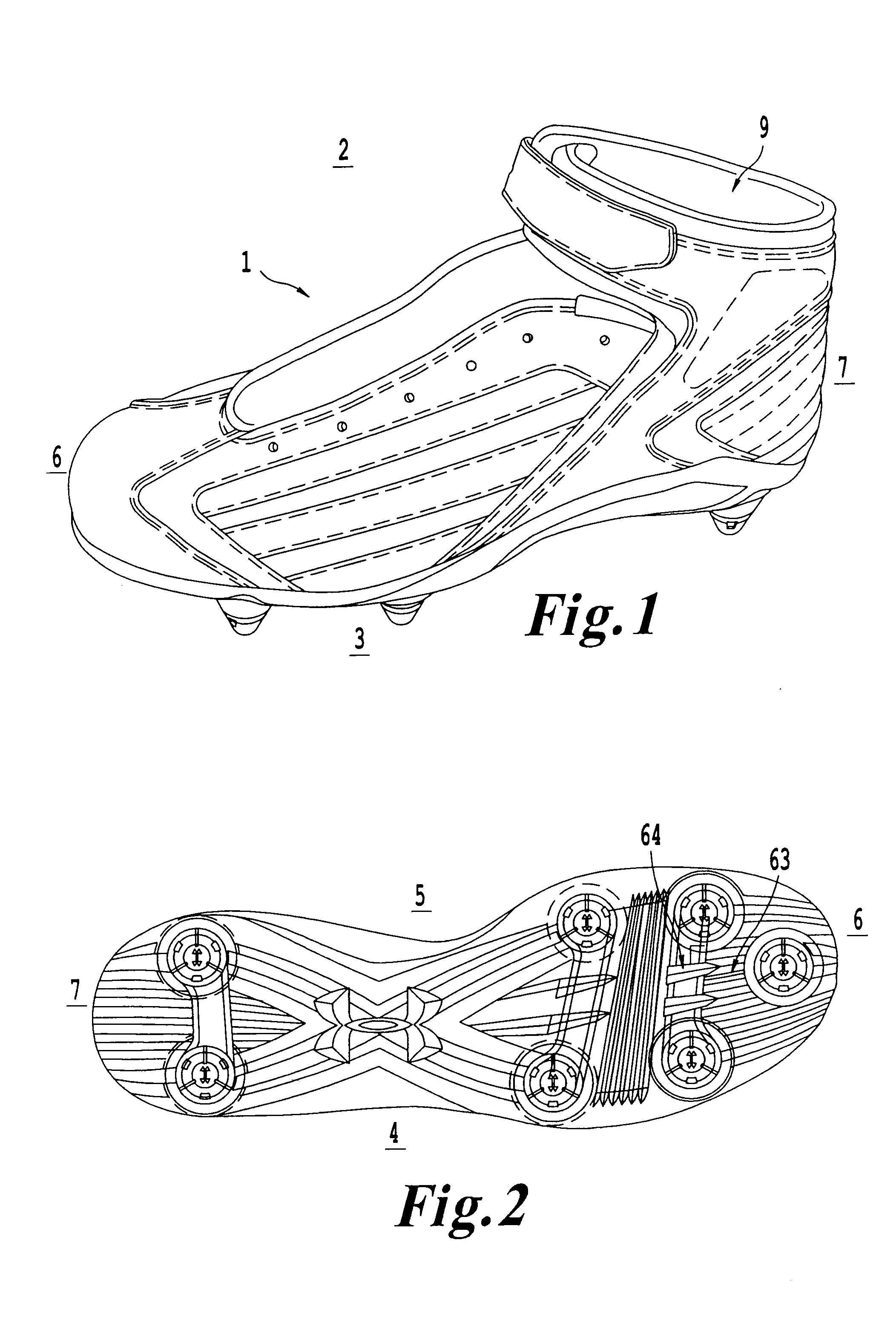
[0040]FIG. 5 illustrates an outsole 60 consistent with embodiments of the invention. The outsole 60 may include a hollow raised protrusion 70 where a cleat 50 may be attached. The outsole 60 may include a top outsole surface 61 and a bottom outsole surface 62. FIG. 2 illustrates that the outsole may have groove...

second embodiment

[0049]The outsole 260 consistent with the second embodiment may include solid raised protrusions 270 where a cleat 50 may be attached. The outsole 260 may include a top outsole surface 261 and a bottom outsole surface 262, as well as grooves 63, 64 (not shown) to improve stiffness. The outsole 260 may be made of polyurethane material, thermoplastic urethane, or the like.

[0050]FIG. 12A illustrates a close-up of the solid raised protrusion 270 from the medial side 5 consistent with the second embodiment of the invention. The outsole 260 is formed with a solid protrusion 270 having a bottom raised surface 271, an outsole inner bore 272, and an outsole opening 273. The solid raised protrusion may be made of the same material or a different material as to the rest of the outsole 260 and may include a disk cylinder 280 integrated as part of the solid raised protrusion 270. The disk cylinder 280 includes a support disk 281 attached to a hollow cylindrical body 282. The hollow cylindrical b...

third embodiment

[0053]the present invention is shown in FIG. 14, may include a primary midsole 30 having a sunken surface 40, a cushion 90, an outsole 160, and a cleat 150.

[0054]The cleat 150 may be molded to the outsole 160. The cleat 150 may include a bottom cleat surface 151. The primary midsole 30 may be attached to the outsole 160 so that the cleat 150 may be positioned under the cushion, when the cushion 90 is disposed within the sunken midsole area 40 as shown in FIG. 14. The sunken midsole area 40 may be sized larger than the cushion 90 to allow for the cushion 90 to expand unobstructed into an empty space 94 when the cushion is compressed by the top surface 161 of the outsole 160. The cushion 90 may be located only above the cleat 150.


PUM


Abstract

A cleated shoe is presented which provides cushion support and lateral stability in a lightweight construction. The shoe includes a lower and an upper. The lower may include a primary midsole, cushion elements, and an outsole. A cleat may be connected to the outsole. At least one cushion may be located between the primary midsole and outsole. Various embodiments of cushions are presented and may be consistent with specific types of shoes associated with various types of activities such as football, baseball, lacrosse, soccer, or golf. The lower may be consistent with approaches to remediate a wearer's pronation or supination.

Description

BACKGROUND[0001]1. Field of the Invention[0002]This invention relates to footwear having an upper and a lower, more specifically to a cushion structure integrated as part of a cleat included in the lower.[0003]2. Description of the Related Art[0004]The modern shoe is a system of various parts, all contributing an important part to the performance of the athlete and to the support, comfort, and protection of the athlete's foot. There are specialized shoes designed for athletes in very different activities from: football, baseball, lacrosse, soccer, and golf. Each of these activities require a special blend of performance specifically tied to weight, traction, support, comfort, and protection. Shoes may also be customized for the user's physical characteristics such as the user's weight, shoe size and gait (i.e. pronated, supinated, neutral). Specifically, the weight, cushioning, and lateral stability characteristics of a shoe can be a strong determinant of performance because they ma...

Claims


Application Information

Patent Timeline
IPC IPC(8): A43B5/00A43B13/12A43B13/18A43C15/00
CPCA43B7/142A43B7/143A43B7/144A43C15/168A43B13/188A43B13/189A43B13/26A43B7/145
Inventor CAMPBELL, DEREKFISHER, KEVINWHITE, MICHAEL N.
Owner UNDER ARMOUR
Why Eureka
Try Eureka