Corrugated Micro Tube Heat Exchanger

Inactive Publication Date: 2010-09-16
INT MEZZO TECH
View PDF99 Cites 12 Cited by
  • Summary
  • Abstract
  • Description
  • Claims
  • Application Information

AI Technical Summary

Benefits of technology

[0006]The present invention provides an efficient, simple, and cost-effective device and/or methodo

Problems solved by technology

For example, in the case of a liquid-gas heat exchanger, a typical design challenge is to minimize the face area associated with the gas side duct, while simultaneously meeting given specifications relating to allowable pressure drop of the gas across the heat exchanger, and, of course, heat transfer requirements.
Upon

Method used


Image

  • Corrugated Micro Tube Heat Exchanger
  • Corrugated Micro Tube Heat Exchanger
  • Corrugated Micro Tube Heat Exchanger

Examples


Embodiment Construction

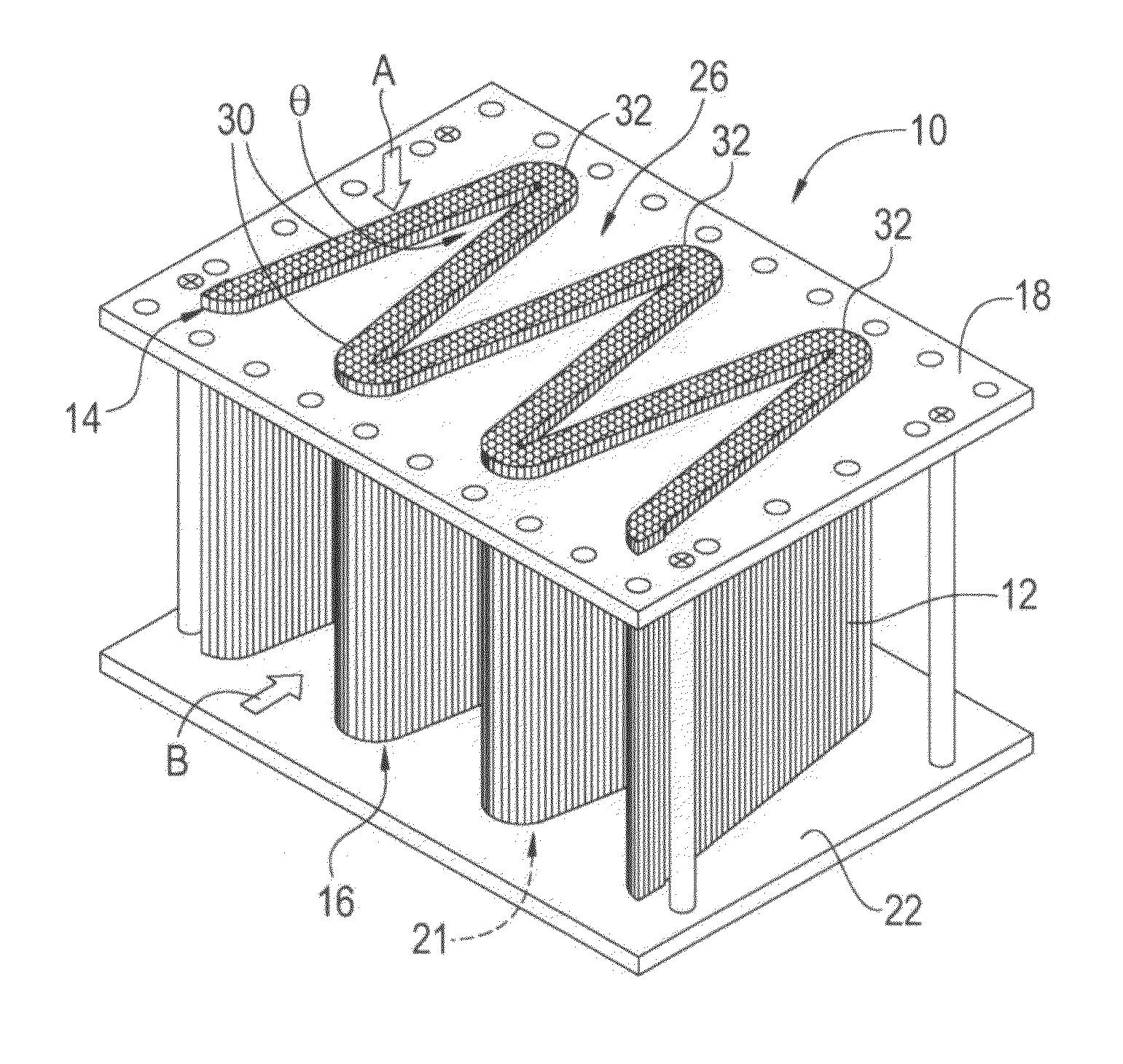
[0021]The present invention enables the exchange of energy from one fluid to another in a heat exchanger without a significant reduction in pressure across the core while offering high heat transfer to weight ratio and reduced volume of the core. It does so by employing a device and / or methodology which is cost-effective and offers a relative ease of manufacture.

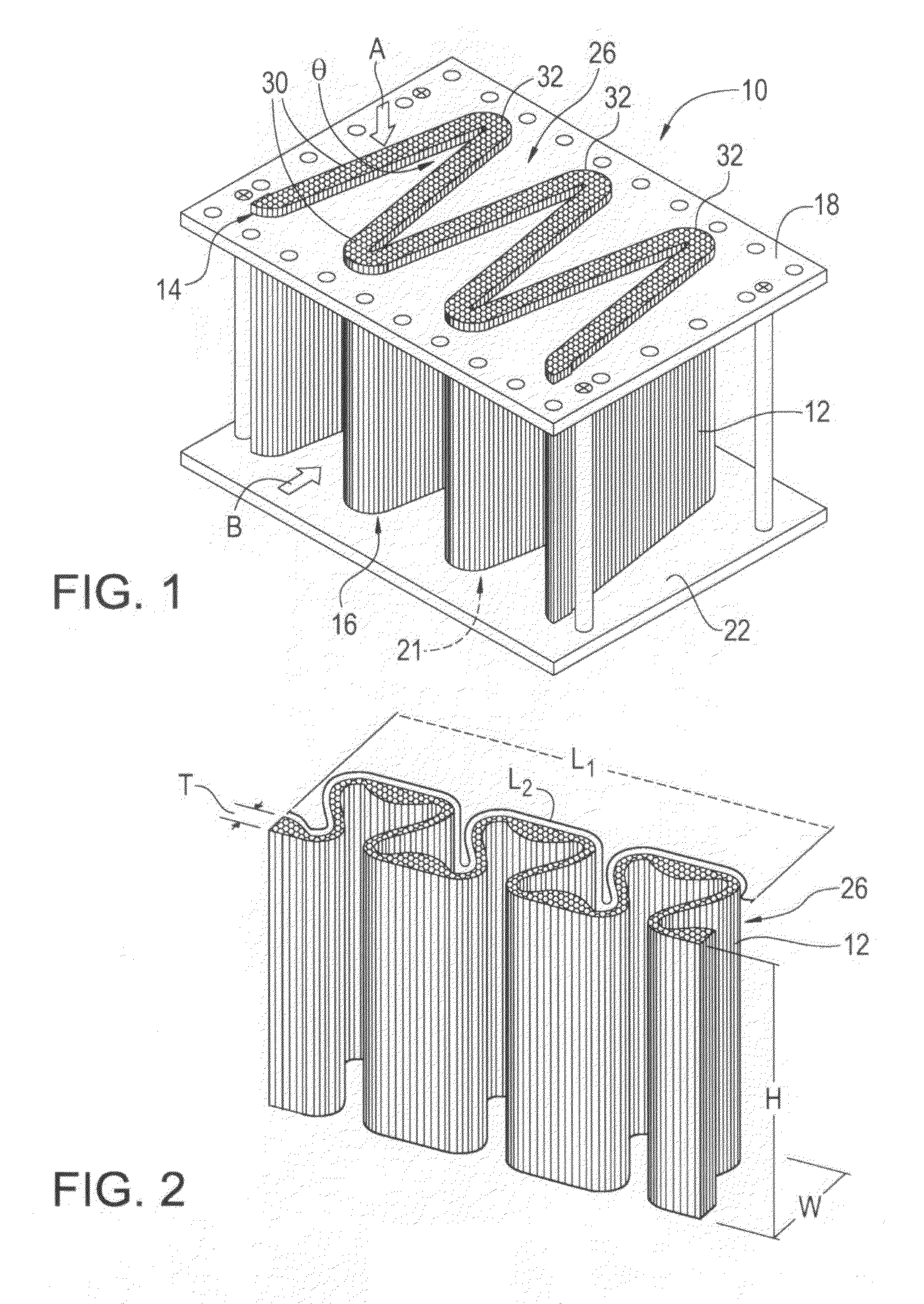
[0022]Referring now descriptively to the drawings, the attached figures illustrate one particular embodiment of the invention, in which a heat exchanger device 10 comprises corrugated micro tubes 12. As seen in FIG. 1, the illustrated embodiment has a plurality of substantially parallel tubes 12 in fluid communication with a first manifold 18 and a second manifold 22. Each parallel tube 12 has an outer diameter D (see FIG. 5) of less than or equal to one millimeter and further comprises a first end portion 14 and a second end portion 16.

[0023]First manifold 18 forms an inlet (not shown) for the first fluid A. First manifold ...


PUM


Abstract

A heat exchanger device having a plurality of substantially parallel tubes. Each tube has an outer diameter which is less than or equal to one millimeter and further includes a first end portion and a second end portion. A first manifold forms an inlet for the first fluid and further forms a plurality of first openings, whereby each of the first end portions of the parallel tubes is attached in a sealed manner to the first manifold so that each tube is in fluid communication with a respective one of the first openings. A second manifold spaced from and opposing the first manifold forms an outlet for the first fluid and further forms a plurality of second openings, whereby each of the second end portions of the parallel tubes is attached in a sealed manner to the second manifold so that each tube is in fluid communication with a respective one of the second openings. The plurality of substantially parallel tubes are laterally disposed relative to one another so that they form at least one corrugated pattern when viewed in an imaginary plane which intersects and is perpendicular to the longitudinal axes of the tubes.

Description

REFERENCE TO RELATED APPLICATIONS[0001]This application claims the benefit of U.S. Provisional Application No. 61 / 019,911, filed Jan. 9, 2008, the disclosure of which is incorporated herein by reference.TECHNICAL FIELD[0002]This invention relates to a heat exchanger device comprising corrugated micro tubes.BACKGROUND[0003]Heat exchangers transfer energy from one fluid to another. Heat exchangers are typically characterized by heat transfer rates and corresponding pressure drops of the fluid(s) across the heat exchanger. In many cases though, volume constraints are provided and, in these cases, heat exchanger performance may be characterized by heat transfer / flow area and corresponding pressure drops. For example, in the case of a liquid-gas heat exchanger, a typical design challenge is to minimize the face area associated with the gas side duct, while simultaneously meeting given specifications relating to allowable pressure drop of the gas across the heat exchanger, and, of course,...

Claims


Application Information

Patent Timeline
IPC IPC(8): F28F9/02F28F1/10
CPCF28F2260/02F28D1/05333
Inventor BECNEL, CHARLES J.MCLEAN, JEFFREY JOHN
Owner INT MEZZO TECH
Why Eureka
Try Eureka