Crane control with active heave compensation

a crane and active heave technology, applied in the field of crane control with active heave compensation, can solve problems such as delay in reaction, and achieve the effect of precise load positioning

Inactive Publication Date: 2010-09-16
LIEBHERR WERK NENZING
View PDF6 Cites 94 Cited by
  • Summary
  • Abstract
  • Description
  • Claims
  • Application Information

AI Technical Summary

Benefits of technology

[0009]Beside the predicted movement of the load suspension point, the desired path of the load is of course also included in the path control of the load, which is generated by a path planning unit e.g. on the basis of control commands of an operator or on the basis of an automatically provided course of hoisting. In accordance with the invention, the path control now ensures that the path of the load provided by the path planning unit is maintained despite the movement of the load suspension point, which is caused by the heave movement of the floating body. By means of the crane control of the invention, an exact positioning of the load can thus be ensured. Furthermore, it is ensured that there are no overloads of the rope or the crane during the hoisting operation.
[0010]Advantageously, the model of the heave movement as used in the prediction device is independent of the properties, in particular of the configuration and dynamics of the floating body. In this way, the crane control of the invention can flexibly be used for a multitude of floating bodys. In particular, the crane hence can be mounted on different ships, without each time having to adapt the heave compensation of the crane control, which would be very expensive in a modeling depending on the properties of the ship. Independent of the properties of the floating body, the model hence is created on the basis of the measured heave movement alone, for which purpose the periodic portions of the heave movement are used. For this purpose, not only the current heave movement, but also the course of the heave movement is analyzed continuously for a certain period.

Problems solved by technology

Actuation merely on the basis of the currently measured movement of the load suspension point hence would lead to a delayed reaction.

Method used


Image

  • Crane control with active heave compensation
  • Crane control with active heave compensation
  • Crane control with active heave compensation

Examples


Embodiment Construction

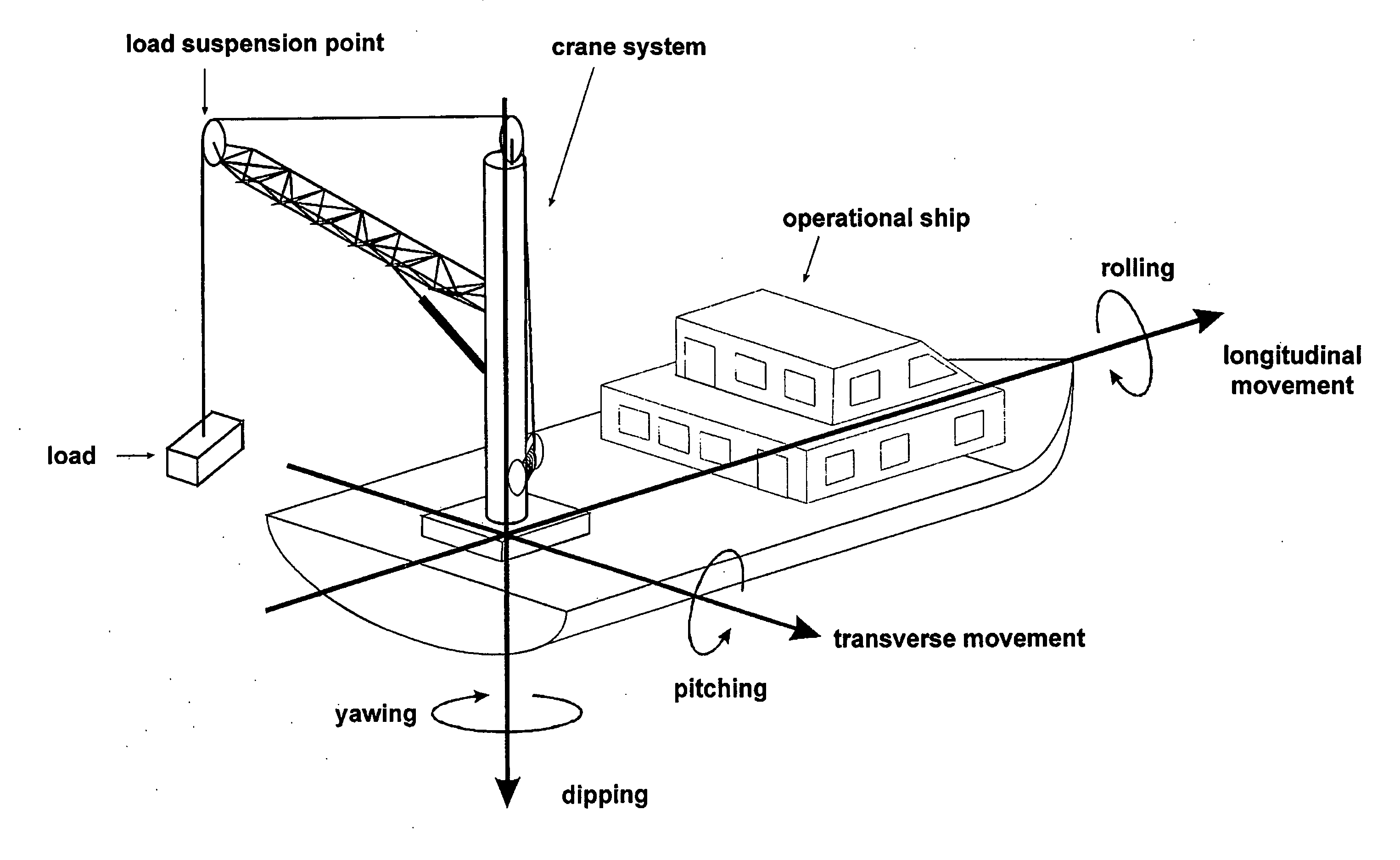
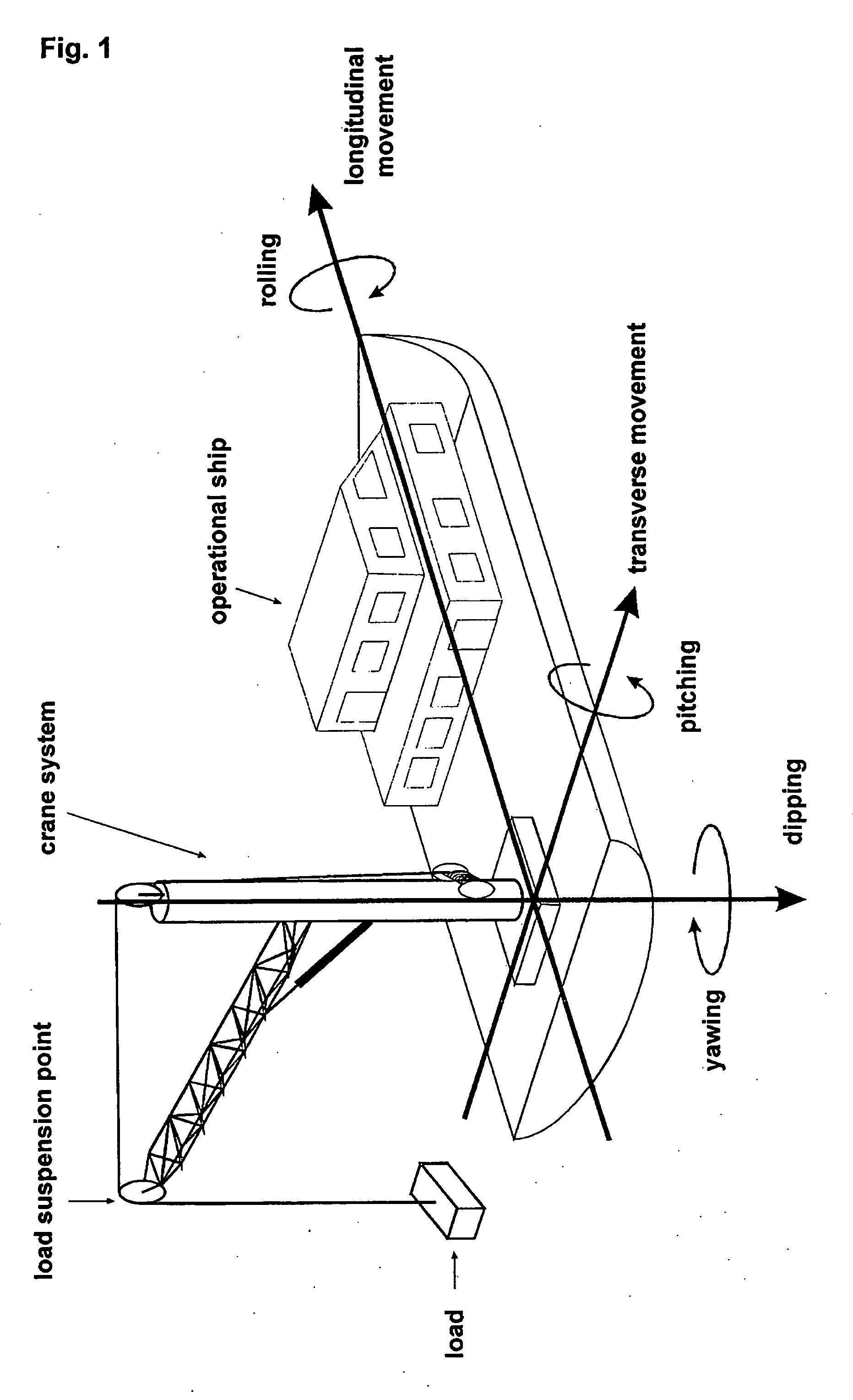
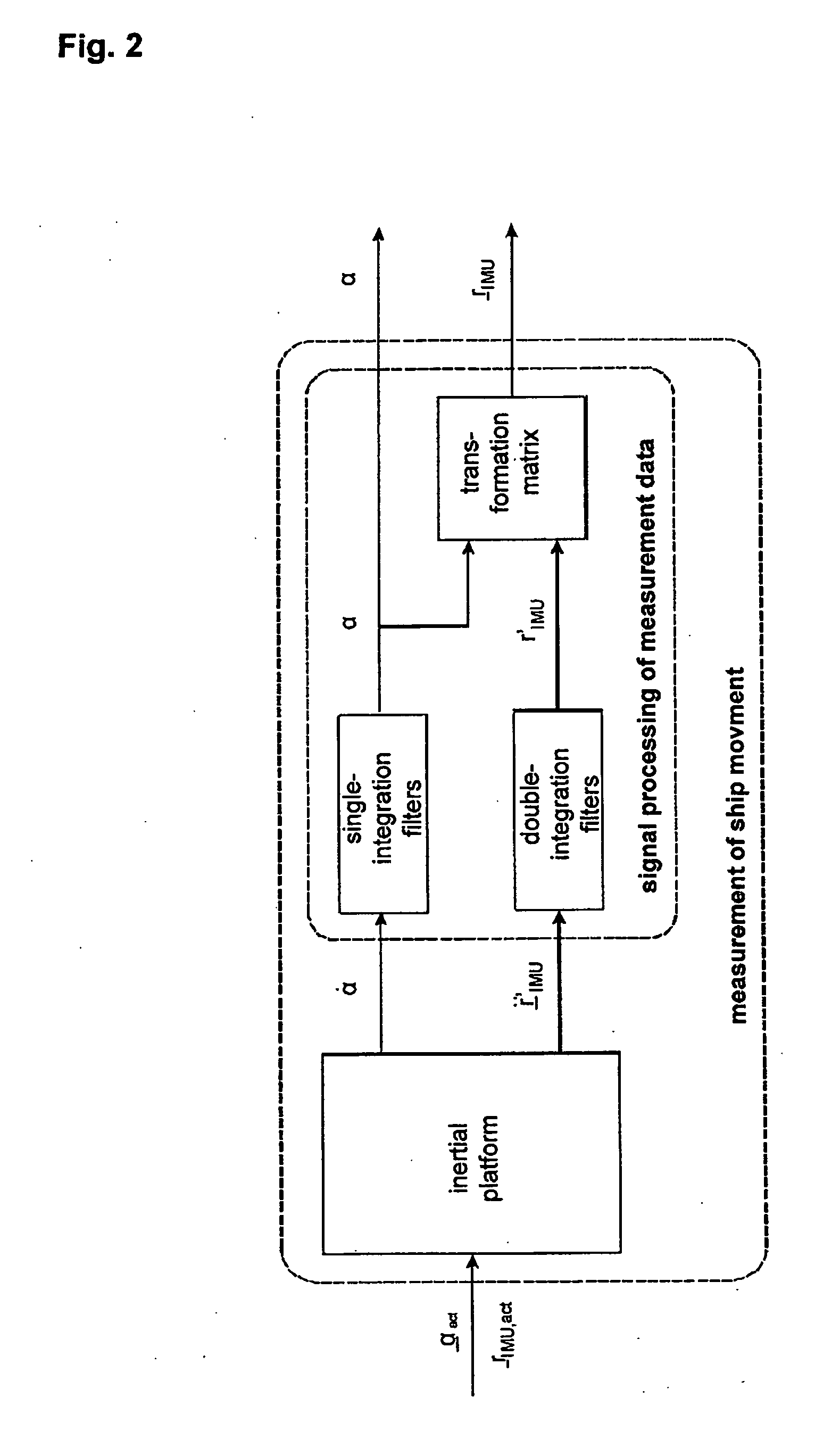
[0043]Now, there is first described an embodiment of a measurement method which on the one hand is based on the measurement of the movement of the ship and on the other hand on the determination of the relative position of the boom tip of the crane system proceeding from its foundation. For the first-mentioned measurement task, an inertial platform is used, which measures the linear accelerations and rotatory rates of rotation about all three axes of the ship. The latter must be performed by the sensors of the crane system. With this measurement arrangement, a measurement of the dip movement free from drift, an extremely small phase shift in the significant frequency range of the dip movement, and a maximum measurement deviation of about 15% of the amplitude of the dip movement is achieved. The embodiment of a method for predicting the dip movement of the load suspension point is based on a model of this movement. Since the model can, however, not be created a priori, the same must ...


PUM


Abstract

The present invention represents a procedure for compensating the heave movement of offshore cranes. The dynamic model of the compensation actuator (hydraulically operated winch) and the load hanging on a rope are derived. Based on this model, a path-tracking control unit is developed. To compensate the movement of the ship/watercraft caused by waves, the heave movement is defined as a time-varying disturbance and is analyzed with respect to uncoupling conditions. With a model expansion, these conditions are satisfied, and an inversion-based uncoupling control law is formulated. To stabilize the system, an observer is used for reconstructing the unknown state by means of a force measurement. Furthermore, the compensation efficiency can be improved by predicting the heave movement. There is proposed a prediction method in which no ship/watercraft models or properties are required. The simulation and measurement results validate the heave compensation method.

Description

BACKGROUND OF THE INVENTION[0001]The present invention relates to a crane control with active heave compensation for a crane arranged on a floating body, which includes a hoisting gear for lifting a load hanging on a rope.[0002]Such crane controls are required to compensate the undesired influences of the sea waves on the movement of the load, which otherwise impair the safety and accuracy of the hoisting operation, in a crane mounted on a floating body, such as a ship, a semi-submersible platform or a bark.[0003]For the installation of offshore wind parks and underwater extraction plants, an increasing demand of floating cranes exists, so that crane controls with heave compensation have a particular importance. Such crane control should provide for a safe, exact and efficient operation of the crane also under poor weather conditions with great heave, in order to minimize the weather-related downtimes. In addition, the safety of both operating personnel and equipment should be ensur...

Claims


Application Information

Patent Timeline
Patent Type & Authority Applications(United States)
IPC IPC(8): B66C13/04G06F19/00B66C23/52B66C13/18
CPCB63B27/10B66C23/52B66C13/063B63B2017/0072
Inventor SCHNEIDER, KLAUSSAWODNY, OLIVERNEUPERT, JOERGMAHL, TOBIASKUCHLER, SEBASTIAN
Owner LIEBHERR WERK NENZING
Why Eureka
Try Eureka