Nail Box for T-shaped, L-shaped and U-shaped Nails of Nail-Shooting Gun

a nail box and nail gun technology, applied in the field of nail box of nail gun, can solve the problem of reducing the service life of the entire nail box, and achieve the effect of reducing the range of application, avoiding abrasion of the containing groove in the nailing box, and convenient for users

Inactive Publication Date: 2010-09-16
TAIZHOU DAJIANG IND
View PDF16 Cites 16 Cited by
  • Summary
  • Abstract
  • Description
  • Claims
  • Application Information

AI Technical Summary

Benefits of technology

[0004]The present invention aims to solve the above technical problem, and provide a nail box with higher abrasion resistance for T-shaped, U-shaped and L-shaped nails of nail-shooting gun with lower costs.
[0018]Compared with the prior art, the advantages of the technical solution provided by the present invention are as follows: the nail box can be applied for T-shaped, L-shaped and U-shaped nails of nail-shooting gun, due to two convex stripes are applied on the top of the nail containing groove enclosed by the groove seat and the nail clamp, so that the application range of the nail box can be extended for T-shaped, U-shaped and L-shaped nails, and the nail box is more convenient for users; meanwhile, as the inlaid stripes structure is applied, the abrasion of the containing groove in the nailing box may be avoided, the service life of the entire nail box can be largely increased, the cost of the nail box is reduced, and the steadiness of nail feeding is improved.

Problems solved by technology

The disadvantages of the technical solution disclosed above are that the prior nail box is only suitable for the T-shaped and the U-shaped nails, while not suitable for the L-shaped nails; and the above-mentioned patent document No.
: CN2340569Y does not disclose the technical designs that the abrasion resistance of channel materials can be higher than that of the groove seat and the sliding box, so the groove channels may be the first to be frayed in nailing operation, more particularly in high-frequency nailing operation, thereby the service life of the entire nail box will be reduced.

Method used


Image

  • Nail Box for T-shaped, L-shaped and U-shaped Nails of Nail-Shooting Gun
  • Nail Box for T-shaped, L-shaped and U-shaped Nails of Nail-Shooting Gun
  • Nail Box for T-shaped, L-shaped and U-shaped Nails of Nail-Shooting Gun

Examples


Embodiment Construction

[0025]Hereinafter, embodiments of the present invention will be described with reference to the accompanying drawings.

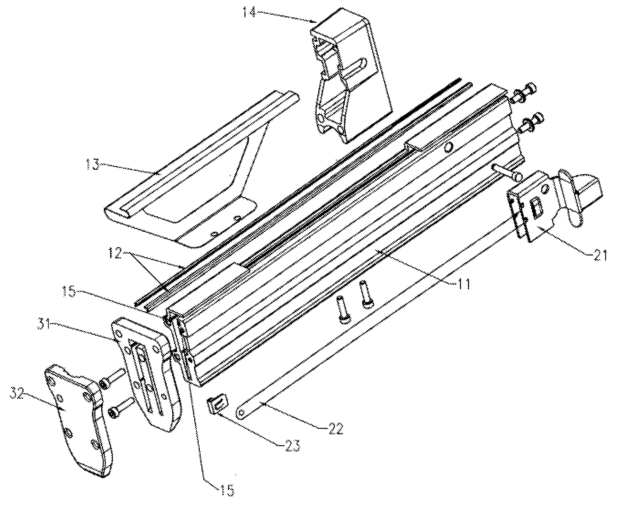
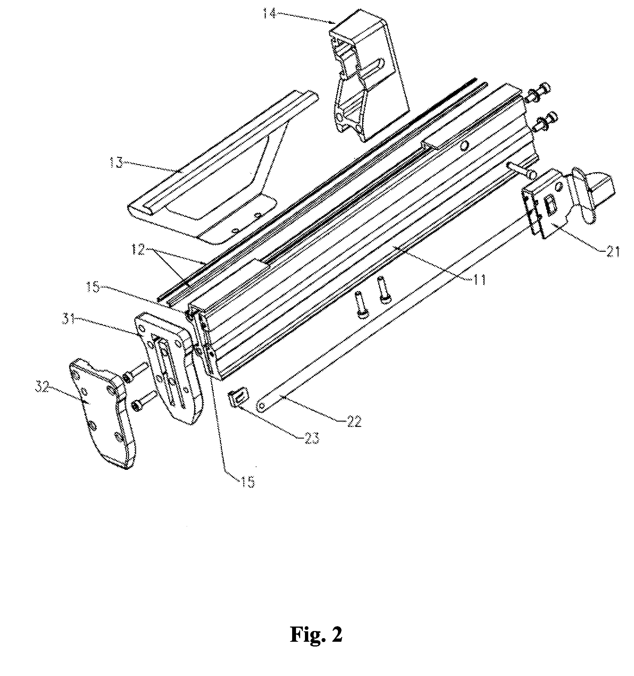
[0026]Referring to FIGS. 1 and 2, a nail box 10 with higher abrasion resistance for T-shaped, L-shaped and U-shaped nails of nail-shooting gun according to the present invention comprises:

[0027]A nail clamp 11, which having a containing groove P to be passed by T-shaped, L-shaped or U-shaped nails. One end of the nail clamp 11 is arranged with a bracket 14, and the opposite end of the groove seat 16 and the nail clamp 11 is connected with the head 30 of a nail-shooting gun;

[0028]a nail-pushing block 21, which is matched with the nail clamp 11, and is connected with the head 30 of the gun body of the nail-shooting gun by an elastic element 22 for pushing T-shaped, L-shaped or U-shaped nails to move toward the head 30 of the nail-shooting gun along the containing groove P,

[0029]A nail clamp protective shell 13, which is arranged glidingly on the exterior of the nail cl...


PUM


Abstract

The present invention discloses a nail box for T-shaped, L-shaped and U-shaped nails of nail-shooting gun, comprising: a groove seat provided to be straddled and slid by the U-shaped nails, one end of the groove seat is connected with the head of the nail-shooting gun; a nail clamp arranged at a side face of the groove seat to form a containing groove between the nail clamp and the groove seat to be passed by a nail; a nail-pushing block having an U-shaped cross section and connected with the body of the nail-shooting gun by an elastic element to push the nail to move toward the head of the nail-shooting gun along the containing groove; characterized in that: two convex stripes are oppositely arranged on an inner wall of the containing groove adjacent to the top of the groove seat. The usage range of the nail box according to the present invention can be extended, and the nail box is more convenient for users.

Description

FIELD OF THE INVENTION[0001]The present invention relates to a nail box of nail-shooting gun, and more particularly, to a nail box suitable for T-shaped, L-shaped and U-shaped nails of nail-shooting gun.BACKGROUND OF THE INVENTION[0002]Referring to a structure of the prior nail-shooting gun, the nail box is developed relatively mature enough to be suitable for an alternative utilization of T-shaped and U-shaped nails, or for an alternative utilization of T-shaped and L-shaped nails, or for an alternative utilization of U-shaped and L-shaped nails. However, in company with extending of application range of nail-shooting gun and increasing of the nail shapes, operation practice puts forward more advanced requests for versatility of the nails setting in the nail box. In nailing operation, nail box may be required to be not only suitable for an alternative utilization of T-shaped and U-shaped nails, or for an alternative utilization of T-shaped and L-shaped nails, or for an alternative ...

Claims


Application Information

Patent Timeline
Patent Type & Authority Applications(United States)
IPC IPC(8): B25C1/00
CPCB25C5/1651B25C1/005
Inventor YANG, MINGJUN
Owner TAIZHOU DAJIANG IND
Why Eureka
Try Eureka