Vehicle impact detection system

a detection system and vehicle technology, applied in the direction of roofs, transportation and packaging, vehicle arrangements, etc., can solve the problems of inability failure to accurately transmit impact load to impact sensors located in the center in the vehicle-width direction, and failure to accurately transmit impact load to impact sensors. to achieve the effect of accurately transmitting the load produced

Active Publication Date: 2010-09-16
MITSUBISHI MOTORS CORP
View PDF5 Cites 47 Cited by
  • Summary
  • Abstract
  • Description
  • Claims
  • Application Information

AI Technical Summary

Benefits of technology

[0010]The present invention has been made to solve the above-mentioned problem. It is an object of the invention to provide a vehicle impact detection system capable of accur

Problems solved by technology

Concerning an occupant protection device like the one mentioned above, however, the curtain and side airbags and the like might fail to be actuated even if the load is inputted from the outside in the vehicle-width direction in the event of a side impact crash (especially a collision with a pole).
This is because an impact area is locally deformed due to small contact area between the impacted object (pole) and the vehicle body, and this local deformation of the impact area consumes impact energ

Method used


Image

  • Vehicle impact detection system
  • Vehicle impact detection system
  • Vehicle impact detection system

Examples


first embodiment

[0024]A first embodiment will be described first.

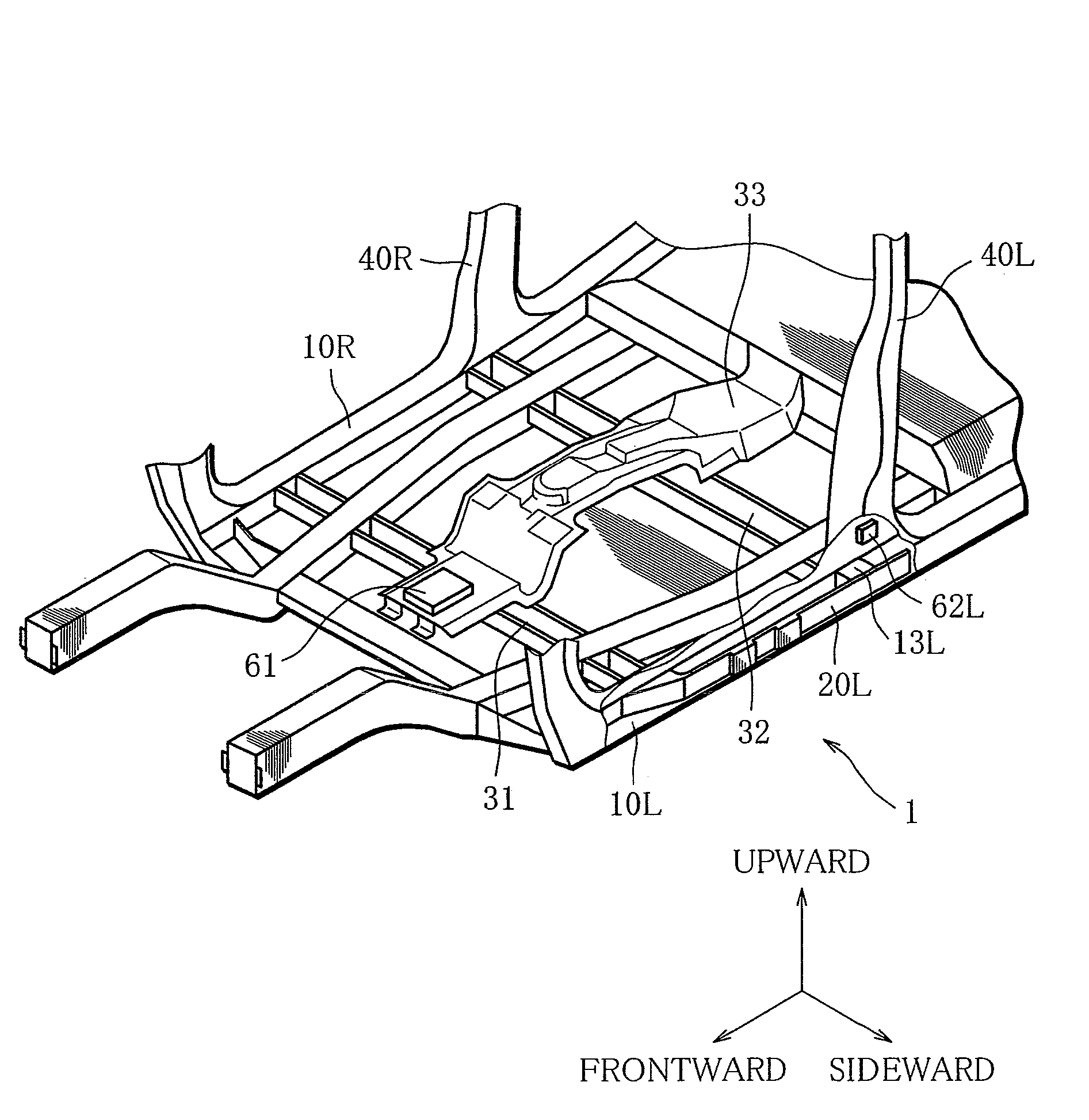
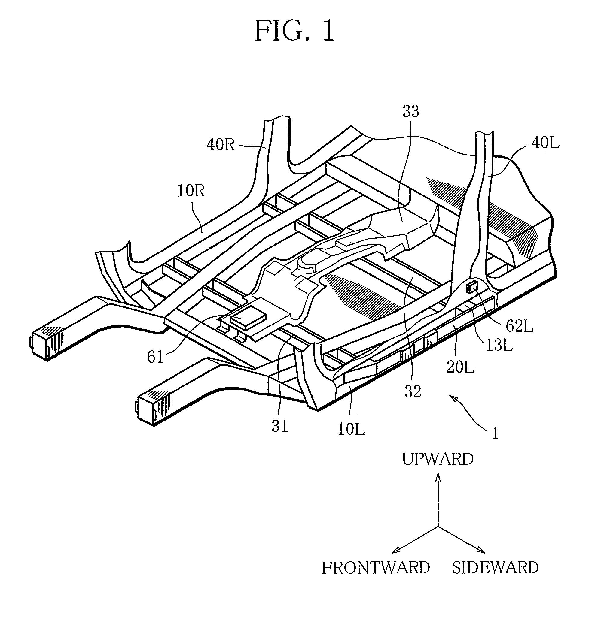
[0025]FIG. 1 is a schematic configuration view of a vehicle impact detection system according to the first embodiment of the invention. FIG. 2 is a top view of the vehicle impact detection system. FIG. 3 is a cross-section across line A-A, and FIG. 4 across line B-B. FIGS. 3 and 4 are detailed views of the vehicle impact detection system according to the invention.

[0026]In the drawings, arrows “FORWARD” and “UPWARD” indicate forward and upward directions, respectively, of the vehicle body. An arrow “SIDEWARD” indicates an inward direction of a vehicle-width direction. Reference marks R and L in the drawings mean right and left, respectively. FIGS. 3 and 4, however, omit these reference marks R and L.

[0027]The configuration of the vehicle impact detection system will be described below.

[0028]As shown in FIGS. 1 to 4, a vehicle referred to in the present embodiment is of a monocoque construction.

[0029]Side sills 10R and 10L are framewor...

second embodiment

[0044]A second embodiment will be described below.

[0045]FIG. 5 is a schematic configuration view of a vehicle impact detection system according to the second embodiment of the invention. FIG. 6 is a top view of the vehicle impact detection system. FIG. 7 is a cross-section across line C-C, and is a detailed view of the vehicle impact detection system according to the invention. In FIG. 7, reference marks R and L are omitted.

[0046]The second embodiment differs from the first in that air dams 50R and 50L are added to the first embodiment. The following description explains different points from the first embodiment.

[0047]As shown in FIGS. 5 to 7, the resin air dams 50R and 50L extending in the vehicle front-rear direction are fixed to outer sides of the side sills 10R and 10L in the vehicle-width direction. The drawings do not show the air dam 50R, but show the air dam 50L representing the both. The air dams 50R and 50L each have a cross section structure that is open inwards in the v...


PUM


Abstract

A side sill beam having a shape of an arch concave outwards in a vehicle-width direction is placed in a side sill, and includes first and second ends welded to joining areas with front and rear floor cross members, respectively. A first impact detection element that detects an impact from the outside in the vehicle-width direction is disposed near the joining areas of the side sill and the front or rear floor cross member, and a second impact detection element that detects an impact from the outside in the vehicle-width direction is disposed offset from the first impact detection element in a vehicle front-rear direction as viewed in the vehicle-width direction.

Description

BACKGROUND OF THE INVENTION[0001]1. Field of the Invention[0002]The invention relates to a vehicle impact detection system, and more specifically, to a system for transmitting an impact to the side of a vehicle body.[0003]2. Description of the Related Art[0004]Vehicle occupant protection devices that have been used include a curtain airbag and a side airbag that detect an impact in the event of a side impact crash and then deploy between an occupant and the vehicle body.[0005]The curtain airbag, the side airbag and the like are actuated in response to a command from an airbag ECU after load (deceleration) caused in the event of a side impact crash was detected by two impact sensors located in the side part of the vehicle body and in the center in the vehicle-width direction, and the impact was sensed by the airbag ECU.[0006]Concerning an occupant protection device like the one mentioned above, however, the curtain and side airbags and the like might fail to be actuated even if the l...

Claims


Application Information

Patent Timeline
IPC IPC(8): B62D25/02
CPCB62D25/025B62D21/157
Inventor YOSHIOKA, HIDEKIOKAMOTO, TOSHIMASAYAKATA, TAKASHIINAGAKI, TOMOHIROSUGANO, NAOMI
Owner MITSUBISHI MOTORS CORP
Why Eureka
Try Eureka