
Device and method for coding a data signal and device and method for decoding a data signal

a data signal and data signal technology, applied in the field of data signal coding devices, can solve the problems of reducing the amount of data to be transferred, high distortion loss of information transferred, etc., and achieve the effect of improving the quality of the reconstructed data signal

Inactive Publication Date: 2010-09-16
KONINKLIJKE PHILIPS ELECTRONICS NV
View PDF13 Cites 13 Cited by
  • Summary
  • Abstract
  • Description
  • Claims
  • Application Information

AI Technical Summary

Benefits of technology

[0008]The invention aims to improve the quality of the reconstructed data signal

Problems solved by technology

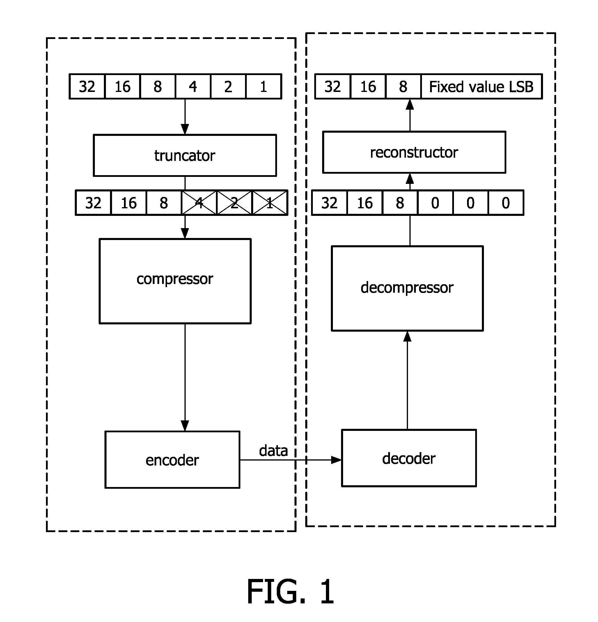
Quantization, for instance truncating a number of least significant bits before compression, reduces the amount of data to be transferred, at a loss in information transferred.
The disadvantage of using known methods for encoding and decoding is that they often result in a consider

Method used


Image

  • Device and method for coding a data signal and device and method for decoding a data signal
  • Device and method for coding a data signal and device and method for decoding a data signal
  • Device and method for coding a data signal and device and method for decoding a data signal

Examples


example a

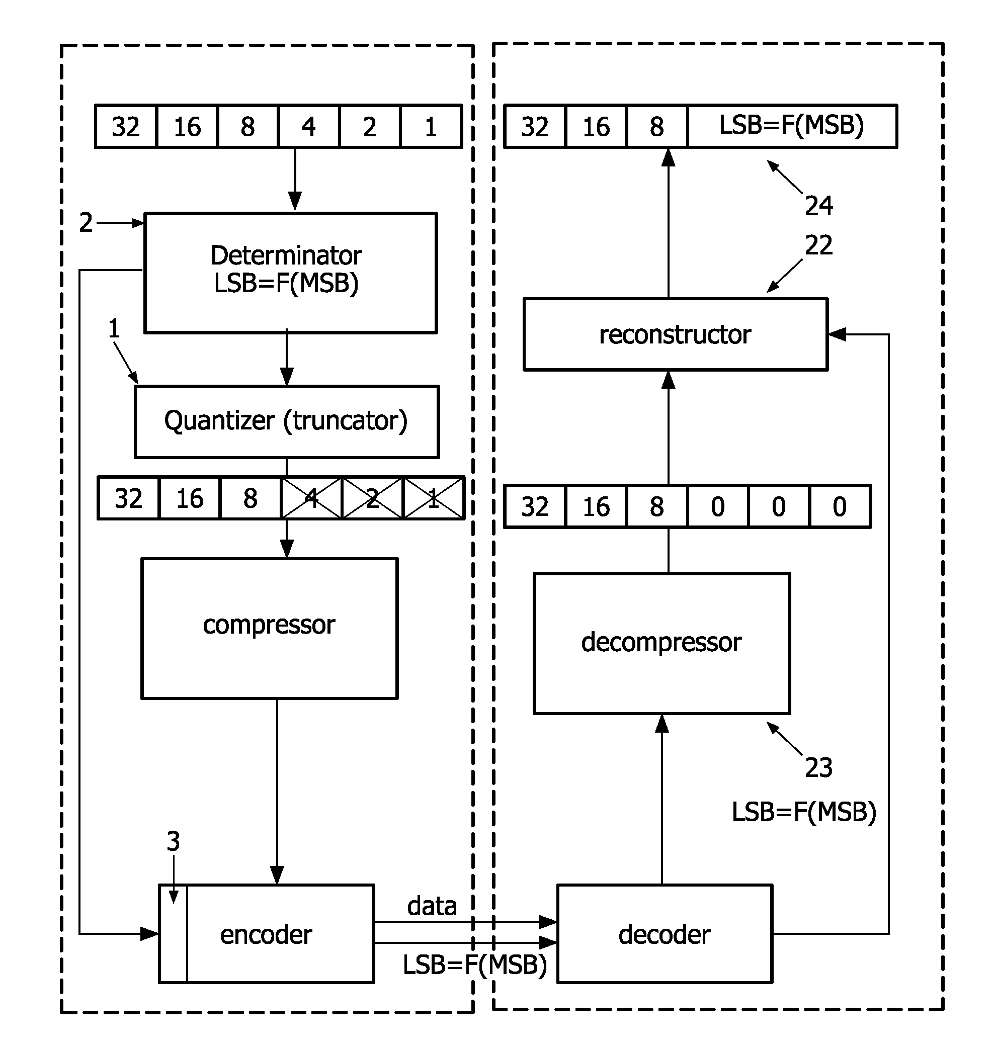
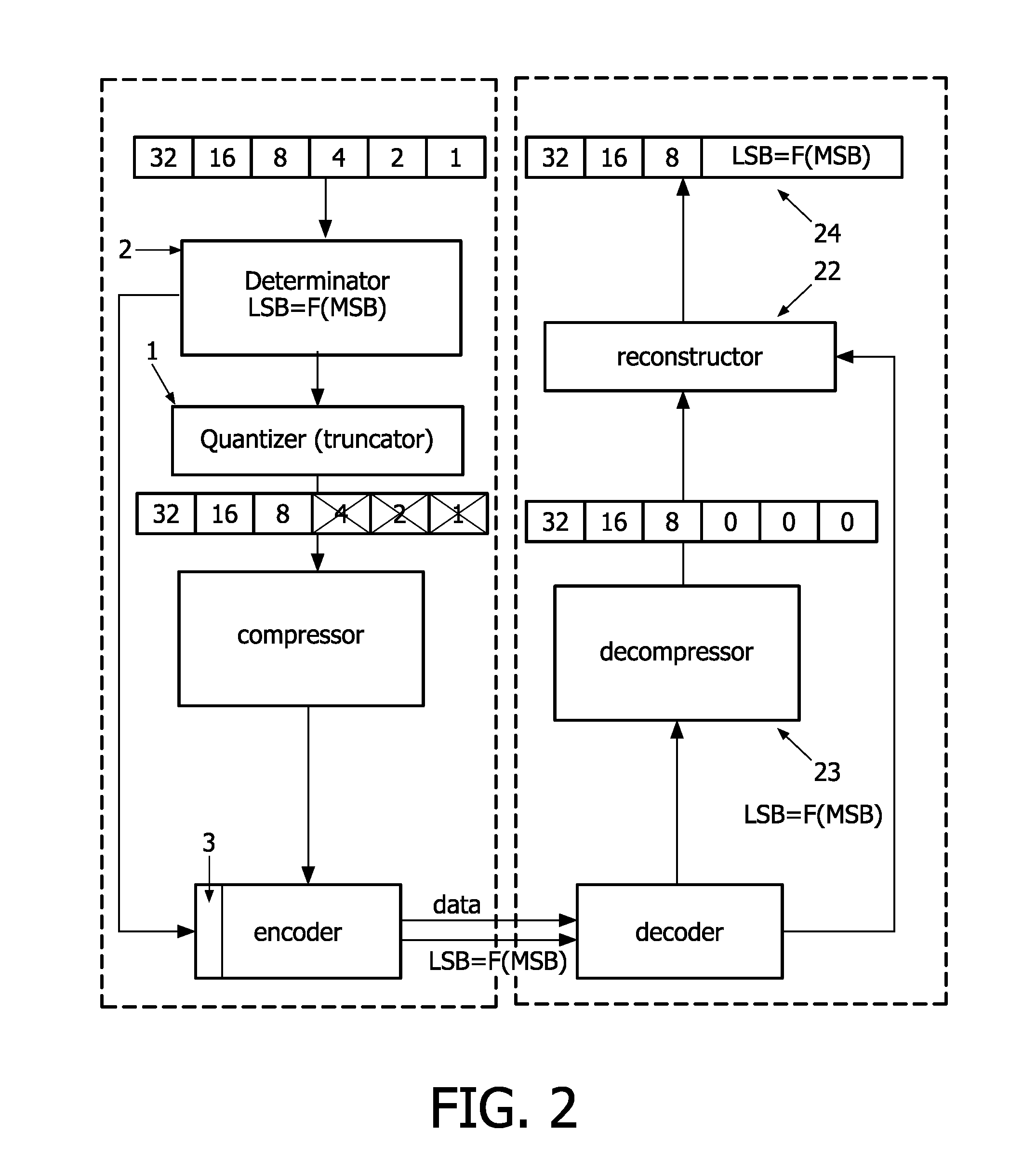
[0050]If for a DCT coefficient with a scalar quantizer of 10 for a given picture the DCT value is 32±2 (with a gaussian distribution) over the picture, the standard method will provide a single value: 100% having a quantized value of 3. The decoder will, at the decoder end, multiply the value with the quantized data interval (=10), and add 5 (=0.5 times the quantized data interval) to the result, giving a single result: 35. The average has then be changed from the original 32 to the reconstructed 35 leading to image errors.

example b

[0051]If for a DCT coefficient with a scalar quantizer of 10 for a given picture the DCT value is 30±4 (with a gaussian distribution) over the picture, the standard method will provide two values: 50% having a quantized value 2 and 50% having a quantized value 3. The decoder will, at the decoder end, multiply the quantized data value with the quantization data interval (=10) of the scalar quantizer, and add 5 to the result, giving two reconstruction values: 50% of the reconstructed data having a reconstructed value of 25, and 50% having a reconstructed value of 35. The original distribution in values prior to quantization (a gaussian distribution with a width of 4 around a peak value of 30, has thus been reconstructed by two peaks (at 25 and at 35) each lying outside the original distribution. The spread in signal has thus been greatly increased by the quantizing-dequantizing steps. This will lead to image errors.

[0052]In the invention the statistical relation between the quantized ...


PUM


Abstract

In a method for encoding and an encoder statistical information is generated and said statistical information (LSB=F(MSB) about the reconstruction values to be used during reconstruction (sometimes called “inverse quantization”) is added to the encoded data signal. The encoded data signal comprises data information providing information on the relation between parts of the original input data removed during quantization and the quantized data. The decoder and decoding method use the information data during reconstruction. This enables reconstruction values to be used during reconstruction that can adapt to the input data statistics thereby improving data reconstruction and reducing the quantization error. The reconstruction at the decoder is guided by information data which is gathered at the encoder, this information data being derived from determining statistical information on the removed parts of the input data in relation to the after quantization remaining quantized data.

Description

FIELD OF THE INVENTION[0001]The invention relates to a device for coding an input data signal into an encoded data signal, wherein the device comprises a quantizer for quantization of input data, mapping the input data on quantized data intervals, whereby a part of the input data is removed during quantization.[0002]The invention also relates to a device for decoding a data signal wherein said data signal comprises a quantized data signal, wherein the device comprises a reconstructor for reconstructing a part of the data signal removed during quantization.[0003]The invention also relates to a method for coding an input data signal wherein the input data signal is quantized, mapping the input data on quantized data intervals, whereby a part of the input data signal is removed and to a method for decoding a quantized data signal wherein the part of the data signal removed during quantization is reconstructed.[0004]The invention furthermore relates to a data signal comprising quantized...

Claims


Application Information

Patent Timeline
IPC IPC(8): H03M7/00
CPCH04N19/46H04N19/60H04N19/184H04N19/136H04N19/126
Inventor VAN DER VLEUTEN, RENATUS JOSEPHUS
Owner KONINKLIJKE PHILIPS ELECTRONICS NV
Learn More